U.S. Department of Transportation
Federal Highway Administration
1200 New Jersey Avenue, SE
Washington, DC 20590
202-366-4000
The strategies for mitigating narrow bridges are aimed primarily at improving a driver&rsquo s ability to see the narrowed cross section on the bridge, the bridge rail, and the lane lines. Safety benefits are a reduced probability of sideswipe or head-on crashes with other vehicles on the bridge, as well as fewer impacts with the bridge rail and approach guardrail. Operational benefits may result from an increase in driver comfort. A driver who can clearly see these cross-sectional elements is more likely to maintain normal operating speeds or at least not dramatically reduce speeds at the bridge. This is particularly important for maintaining efficient traffic flow on urban freeways and can also reduce the probability of rear-end crashes on high-speed, high-volume highways.
|
Target areas: Any narrow bridge location. Strategy: Advance signing of narrow bridge. Signs can be used to warn drivers in advance of a narrow bridge (Figure 41). In some situations, flashers installed in conjunction with the sign may further increase driver awareness. The MUTCD provides guidance on the size of warning signs for various highway types but notes that larger signs may be used when appropriate. Larger warning signs should be considered for design exception locations. Use of advance warning signs as a stand-alone measure is unlikely to sufficiently mitigate a design exception for bridge width, but at some locations it can be an effective component of a more comprehensive approach. |
|
Target areas: Any narrow bridge location. Strategy: Delineation. Delineation of the narrowed cross section at the bridge is another strategy for providing advance warning. One method that provides very good delineation at night is reflectors or reflector tabs that are placed on the approach guardrail and along the bridge rail (Figure 42). Post-mounted delineators approaching the bridge are another option. Instead of providing just a single point of delineation, such as an object marker, reflectors and delineators allow the driver to better see the cross section narrowing as well as the most narrow segment of the cross section&mdash the bridge. |
|
|
|
FIGURE 41 Signs can be used to warn drivers in advance of a narrow bridge. |
Figure 41 shows a diamond-shaped sign with a black border and the words NARROW BRIDGE in black on a yellow background.
|
|
|
FIGURE 42 Reflector tabs on guardrail. |
Figure 42 is a nighttime photo showing illumination from reflector tabs mounted on the tops of the guardrail along both sides of the road. Reflective sheeting delineates the face of the impact head of the guardrail terminal on either side of the road.
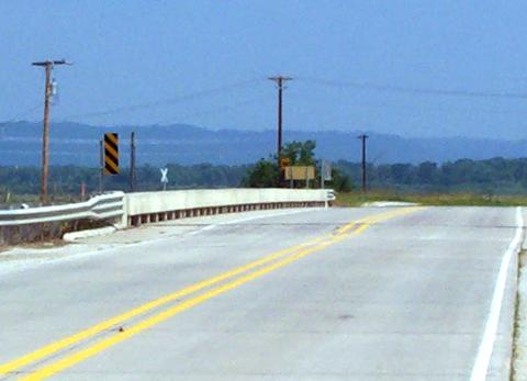
Object markers placed at the ends of the bridge rail is a common treatment (Figure 43). In areas where agricultural equipment or other wide vehicles are using the bridge, one issue to consider when using object markers or other post-mounted signs at the ends of the bridges is that they may prevent this type of equipment from being able to cross the bridge. In these cases, using reflectors on the approach guardrail and the bridge rail or other methods to achieve delineation of the narrow bridge should be considered instead of post-mounted delineation.
|
|
|
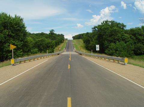
FIGURE 43 Object markers and post-mounted delineators at a narrow bridge. |
|
Figure 43 is a photo of a narrow bridge. Approach guardrail is installed on either side of the road leading to the bridge crossing. Behind the guardrail, closer to the bridge, post-mounted delineators are visible the delineators consist of reflective yellow disks. Where the bridge begins and where the cross section has reached its narrowest point, object markers are posted behind the guardrail. The object markers are rectangular signs with alternating black and yellow diagonal stripes. |
|
Target areas: Any narrow bridge location. Strategy: High-visibility bridge rail. Installing high-visibility bridge rails are another method for delineating narrow bridges. White concrete has been used by some agencies to enhance the visibility of bridge rail at night or when visibility is poor (Figure 44). There are also proprietary products on the market with features that make bridge rails more visible. |
|
|
|
FIGURE 44 White Concrete Bridge Rail. |
Figure 44 is a photo taken on a rainy day showing a curving portion of a bridge that has white concrete bridge rail installed on either side of the road. Its white color makes it easier to see when visibility is poor.
|
Target areas: Narrow bridges in urban areas bridges in areas with a high number of pedestrians and other non-motorized users bridges where traffic volumes are high bridges with a history of crashes or operational problems. Strategy: Lighting at narrow bridges. Lighting is another way to make narrow bridges more visible to drivers. Although most often used in urban areas, lighting may be appropriate on some rural bridges, particularly if there is a history of safety problems. |
|
|
|
|
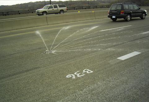
FIGURE 45 Anti-icing system on a bridge. |
Figure 45 is a photo showing an anti-icing solution being sprayed in a fan-shaped pattern across a road from a circular-shaped device that is embedded in the road, flush with the surface of the bridge deck.
|
Target areas: Any narrow bridge location. Strategy: Crashworthy bridge rail and approach guardrail. Because of the higher probability of impacts with the bridge rail and approach guardrail at narrow bridge locations, crashworthy barrier that meets or exceeds NCHRP Report 350 crash test criteria should be used (Figure 46). This includes the bridge rail, the guardrail, the stiffened guardrail transition that connects to the bridge rail, and the guardrail terminal. Safety hardware that complies with Report 350 criteria is required on new installations on the NHS. Upgrading older systems, regardless of highway system, is encouraged&mdash particularly at design exception locations. In areas with high volumes of large vehicles, barrier that has passed test-level 4 or 5 criteria should be considered. Test-levels 4 and 5 include crash tests with single-unit trucks and tractor-semi-trailers, respectively. The AASHTO Roadside Design Guide provides guidance on barrier flare rates. Flared approach guardrail, particularly when combined with reflectors, can visually transition a driver into the narrowed cross section of the bridge (Figure 42. |
|
|
|
FIGURE 46 Bridge rail and guardrail transition in compliance with NCHRP Report 350. |
Figure 46 is a photo showing a bridge with barrier that has passed current crash test standards. W-beam guardrail is installed approaching the bridge, followed by a three-beam guardrail transition, and then a concrete bridge rail.
|
Target areas: Any narrow bridge location. Strategy: Enhanced pavement markings and lane delineation. Other mitigation strategies for narrow bridge width that are discussed in other sections of this chapter include: Enhanced pavement markings: see Lane Width and Shoulder Width section. In addition to the safety benefits of helping drivers see and stay within the lane, improved lane delineation is expected to increase driver comfort at narrow bridges and improve operations. |
|
Target areas: Long bridges. Strategy: Emergency pull-off areas. If a design exception for bridge width cannot be avoided for long bridges, emergency pull-off areas should be considered. Pull-off areas on bridges should be safely terminated, either by flaring the bridge rail at an appropriate rate or through the use of an impact attenuator on any blunt end facing traffic. |
|
Target areas: Long bridges. Strategy: Surveillance. Another strategy for long bridges is to use intelligent transportation systems (ITS) such as cameras to monitor long bridges for crashes, disabled vehicles, or other problems. This will allow law enforcement and other emergency responders to get to the scene as quickly as possible, which may prevent a crash. It also allows a disabled vehicle to be removed from the narrow bridge as quickly as possible, which will improve safety as well as minimize the amount of time a lane is blocked. |