U.S. Department of Transportation
Federal Highway Administration
1200 New Jersey Avenue, SE
Washington, DC 20590
202-366-4000
|
Target areas: Any highway with steep grades. Strategy: Signing. The strategies for mitigating grade are aimed at providing drivers with advance warning as they approach a steep grade, improving the ability of traffic to safely ascend and descend steep grades, and improving drainage in locations with flat grades. |
|
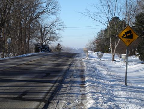
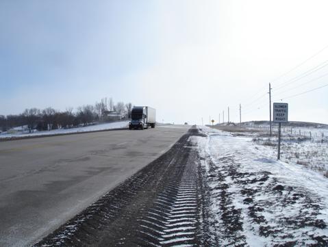
Target areas: High-speed highways with steep grades (most common on rural highways). Strategy: Climbing lanes and downgrade lanes. Signs can be used to warn drivers in advance of steep grades (Figure 52). The MUTCD provides guidance on the size of warning signs for various highway types but notes that larger signs may be used when appropriate. Larger warning signs should be considered for design exception locations. Use of advance warning signs as a stand-alone measure is unlikely to sufficiently mitigate a design exception for grade, but it can be an effective component of a more comprehensive approach. Climbing lanes are a common strategy for improving safety and operations on uphill grades (Figure 53). From an operations standpoint, traffic can continue at free-flow speeds by passing trucks and other slow-moving vehicles. From a safety perspective, providing passing opportunities with a climbing lane reduces the probability of risky passing maneuvers. Similarly, adding a lane on the downgrade side of the facility may also be beneficial in some situations, where large trucks or other slow-moving vehicles create additional risk for faster-moving vehicles approaching from behind. |
|
|
|
FIGURE 53 Advance warning of a steep grade. |
Figure 53 is a photo showing a steep grade warning sign along a road that appears to drop off in the distance. The sign is diamond-shaped with a symbol of a truck pointing to the left and down on a ramp that slopes up from the left to right, with the legend 9% underneath. The sign has black legends and borders on a yellow background.
|
|
|
FIGURE 54 Climbing lane. |
Figure 54 is a photo showing a climbing lane to the right of the primary travel lane on a steep upgrade. A post-mounted sign to the right of the lane contains the words SLOWER TRAFFIC KEEP RIGHT on four lines. The sign is white with black lettering.
|
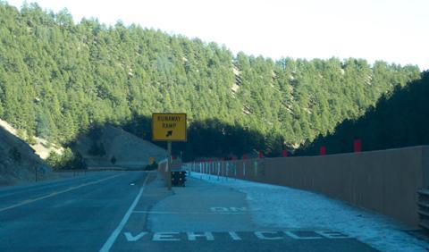
Target areas: High-speed highways with steep grades and high truck volumes (most common in regions with mountainous terrain). Strategy: Escape ramps. For steep downhill grades with large truck volumes, escape ramps can be an effective strategy for capturing heavy vehicles that have lost control (Figure 55). Case Study 2 (presented in Chapter 6) illustrates an innovative truck escape ramp constructed in a mountainous region with very severe grades. |
|
Target areas: Any highway with steep grades. Strategy: Preventing or reducing the severity of lane departure crashes. Strategies should be considered for improving drivers&rsquo ability to stay within the lane or their ability to recover if they leave the lane, and reducing crash severity if the vehicle leaves the roadway. The Lane and Shoulder Width discussion earlier in this chapter has additional information on the following strategies: |
|
|
|
|
FIGURE 55 Truck escape ramp. |
Figure 55 is a photo showing a truck escape ramp on a steep grade that begins to the right of the travel lane and is indicated by a horizontal rectangular sign with the words RUNAWAY RAMP on two lines, with an arrow pointing up and to the right below the words. The sign has a black border and legend on a yellow background. On the right side of the ramp is a retaining wall, on top of which are mounted rectangular red delineators.
|
Target areas: Urban arterials, normally with speeds of 45 mi/h or less. Strategy: Adjusting the gutter profile. For proper drainage of the pavement surface, there needs to be adequate slope in the transverse direction (cross slope) and in the longitudinal direction (grade). To mitigate grades that are too flat, measures should be considered that will improve drainage on the highway. In areas with curbed cross sections, the profile of the gutter can be adjusted by slightly varying the cross slope of the lanes. This creates a " rolling" gutter profile that increases the grade along the curb between inlets, thereby creating more efficient flow and removal of water in the gutter. |
|
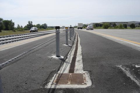
Target areas: High-speed roadways with flat grades areas where fast removal of surface water and minimizing spread onto the roadway is especially important. Strategy: Special drainage systems. In some areas, more expensive drainage systems may be appropriate. Continuous drainage systems can be installed in areas with flat grades (Figure 56). These drains capture the water along the length of the highway segment with flat grades, and the pipe or channel underlying the drain can be sloped to move water efficiently through the system. |
|
|
|
FIGURE 56 Continuous drainage system. |
Figure 56 is a photo of a highway median that contains a continuous drainage channel, covered by a grate that terminates at a grated intake in the foreground of the photo.