U.S. Department of Transportation
Federal Highway Administration
1200 New Jersey Avenue, SE
Washington, DC 20590
202-366-4000
One of the mitigation measures cited in the documentation for the median barrier project was to evaluate the use of a shorter concrete median barrier to maximize horizontal stopping sight distance. Caltrans’ standard median barrier for urban freeways is a single-slope concrete barrier (Figure 118). Barrier as low as 32 inches has been used in other locations and the optimal barrier height is being evaluated for this project.
Several site-specific characteristics are being taken into account. First, large trucks are not permitted on the Arroyo Seco Parkway. Taller barriers typically provide greater performance for containing and redirecting large trucks, but with the truck restriction, this barrier function is not a factor. An additional advantage of taller barriers is that they can shield headlight glare, which can be especially beneficial on a roadway like the Parkway with a curvilinear alignment. A consideration for a location with a historic context is a barrier shape or type that is conducive to aesthetic treatments. Constructability is another factor because some barrier shapes are more efficient to construct through the use of slip-forming equipment.
A shorter median barrier will increase horizontal stopping sight distance. However, a careful weighing of the tradeoffs involved with barrier height will be conducted before a final selection is made.
FHWA’s Roadside Hardware Web site provides information and dimensions on barrier that meets NCHRP Report 350 crash test criteria. The shortest vertical-shaped concrete barrier that meets test-level 3 or 4 criteria is 29 inches. See the following Web site for more information: http://safety.fhwa.dot.gov/roadway_dept/policy_guide/road_hardware/.
|
|
|
FIGURE 118 Single–slope concrete median barrier at a horizontal curve. |
Figure 118 is a photo showing the Caltrans standard median barrier. An oncoming vehicle on the other side of the median is visible over the top of the barrier.
An existing mitigation measure along the Arroyo Seco Parkway for shoulder width is pull–off areas that are provided periodically along the outside (Figure 119). The pull-off areas provide a space for disabled vehicles to pull off the highway, which improves safety and can prevent blocking of through travel lanes. Call boxes with telephones are provided at some of the pull-off areas.
|
|
|
FIGURE 119 Pull-off areas are provided periodically along the outside lanes. |
Figure 119 is a photo showing a paved pull-off area to the right of the outside travel lane with a vehicle in it. The pavement in the pull-off area has diagonal white stripes painted on it.
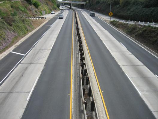
To provide better delineation of the narrow lane and shoulder widths and the horizontal curves, Caltrans has provided enhanced delineation. This includes raised pavement markers, pavement markings with high retroreflectivity, and reflectors along the future concrete median barrier (Figure 120).
|
|
|
FIGURE 120 Enhanced delineation with raised pavement markers and pavement markings with high retroreflectivity. Reflectors will also be placed along the new concrete median barrier. |
Figure 120 is a photo showing yellow, high–reflective pavement markings in conjunction with yellow raised pavement markers to delineate the median-side travel lanes. Double-sided w-beam guardrail is the existing median barrier. This will be replaced by concrete barrier with reflectors. White, high-reflective pavement markings and white raised pavement markers provide improved delineation of the other lanes.
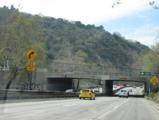
There are a number of advance warning signs along the corridor, both on the mainline and on the ramps (Figure 121). Many of the curve warning signs are combined with advisory speed plaques.
|
|
|
FIGURE 121 Warning signs for curvature, slowing traffic, and vertical clearance. |
Figure 121 is a photo showing warning signs along the Parkway. The first consists of two elements mounted on a pole in the median. The lower element consists of a square sign with a black border and the legend 45 MPH in black on a yellow background. Above it is a diamond-shaped sign with a black arrow curving up and to the left, on a yellow background. The second sign is to the right of the outside travel lane and consists of a pole-mounted diamond-shaped sign with the legend SLOW TRAFFIC AHEAD in black. The third sign is mounted on an overpass bridge and consists of a rectangular sign with the legend VERTICAL CLEARANCE 14’9" in black on a yellow background.
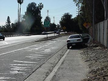
Another project along the Parkway involves improvements to the exit ramp at State Street near the corridor’s northern limits within the city of Pasadena. The ramp has non-standard deceleration length Figure 122), and reconstruction to full criteria is not possible due to the site constraints. In order to improve safety for exiting drivers and drivers behind them, an auxiliary lane is being added upstream of the ramp, parallel to the through travel lanes. This will allow exiting vehicles to decelerate on the auxiliary lane instead of on the outside travel lane.
 |
 |
 |
|
FIGURE 122
|