U.S. Department of Transportation
Federal Highway Administration
1200 New Jersey Avenue, SE
Washington, DC 20590
202-366-4000
This chapter describes guidelines for the signing of horizontal curves. These guidelines were derived from the MUTCD 2009 edition (3) and are intended to complement the procedures for establishing the advisory speed that are described in Chapter 3. Together, the procedure and guidelines provide a rational basis for establishing uniform signing for horizontal curves.
Guidelines for selecting curve related traffic control devices are described in this section and are based on the MUTCD 2009 edition (3). They consist of recommended combinations of traffic control devices associated with the difference between speed limits and advisory curve speeds. The guidelines were developed to reflect a balance of the following goals:
A table in the MUTCD 2003 edition that related sign usage to the advisory speed and number of alignment changes has been replaced by a completely new table that relates sign usage to the difference between the speed limit and the advisory speed.
As shown in the Figure 15 of this report, the criteria in the MUTCD 2009 edition (3) states: "In advance of horizontal curves on freeways, on expressways, and on roadways with more than 1,000 AADT that are functionally classified as arterials or collectors, horizontal alignment warning signs shall be used in accordance with Table 2C-5 based on the speed differential between the roadway's posted or statutory speed limit or 85th-percentile speed, whichever is higher, or the prevailing speed on the approach to the curve, and the horizontal curve's advisory speed...Horizontal Alignment Warning signs may also be used on other roadways or on arterial and collector roadways with less than 1,000 AADT based on engineering judgment."
Application of Table 2C-5. Horizontal Alignment Sign Selection (MUTCD 2009 edition (3)) (see Figure 15 of this report) requires knowledge of the 85th percentile tangent speed for passenger cars. This speed can be obtained from a survey of speeds on a tangent section of highway in the vicinity of the curve. The location at which tangent speed data are collected should be sufficiently distant from the curve that the curve does not influence the observed speeds. If the 85th percentile tangent speed is not available, an equation is provided in the Curve Advisory Speed (CAS) software for estimating this speed.
Figure 15 - MUTCD 2009 Edition Criteria for the Selection of Horizontal Alignment Sign
| Type of Horizontal Alignment Sign | Difference Between Speed Limit and Advisory Speed | ||||
|---|---|---|---|---|---|
| 5 mph | 10 mph | 15 mph | 20 mph | 25 mph or more | |
| Turn (W1-1), Curve (W1-2), Reverse Turn (W1-3), Reverse Curve (W1-4), Winding Road (W1-5), and Combination Horizontal Alignment / Intersection (W10-1) (See section 2C.07 to determing which sign to use) | Recommended | Required | Required | Required | Required |
| Advisory Speed Plaque (W13-1P) | Recommended | Required | Required | Required | Required |
| Cheverons (W1-8) and/or One Direction Large Arrow (W1-6) | Optional | Recommended | Required | Required | Required |
| Exit Speed (W13-2) and Ramp Speed (W13-3) on exit ramp | Optional | Optional | Recommended | Required | Required |
Note: Required means that the sign and/or plaque shall be used, recommended means that the sign and/or plaque should be used, and optional means that the sign and/or plaque may be used. See Section 2C.06 for roadways with less than 1,000 ADT. |
|||||
There is a new table (see Figure 16) added to the MUTCD 2009 edition (3), "Table 2C-6. Typical Spacing of Chevron Alignment Signs on Horizontal Curves."
Figure 16 – MUTCD 2009 Edition Criteria for the Typical Spacing of Chevron Alignment Signs on Horizontal Curves
| Advisory Speed | Curve Radius | Sign Spacing |
|---|---|---|
| 15 mph or less | Less than 200 feet | 40 feet |
| 20 to 30 mph | 200 to 400 feet | 80 feet |
| 35 to 45 mph | 401 to 700 feet | 120 feet |
| 50 to 60 mph | 701 to 1,250 feet | 160 feet |
| More than 60 mph | More than 1,250 feet | 200 feet |
| Note: The relationship between the curve radius and the advisory speed shown in this table should not be used to determine the advisory speed. | ||
To determine the location for installing advance horizontal alignment warning signs, "Table 2C-4. Guidelines for Advance Placement of Warning Signs" in the MUTCD 2009 edition (3) shall be consulted (Refer to Figure 17).
Figure 17 – MUTCD 2009 Edition Criteria for Advance Placement of Warning Signs
| Posted or 85th-Percentile Speed | Advance Placement Distance1 | ||||||||
|---|---|---|---|---|---|---|---|---|---|
| Condition A: Speed Reduction and Lane Changing in Heavy Traffic2 | Condition B: Deceleration to the listed advisory speed (mph) for the condition4 | ||||||||
| 03 | 10 | 20 | 30 | 40 | 50 | 60 | 70 | ||
| 20 mph | 225 ft | N/A5 | N/A5 | — | — | — | — | — | — |
| 25 mph | 325 ft | N/A5 | N/A5 | N/A5 | — | — | — | — | — |
| 30 mph | 450 ft | N/A5 | N/A5 | N/A5 | — | — | — | — | — |
| 35 mph | 550 ft | N/A5 | N/A5 | N/A5 | N/A5 | — | — | — | — |
| 40 mph | 650 ft | 125 ft | N/A5 | N/A5 | N/A5 | — | — | — | — |
| 45 mph | 750 ft | 175 ft | 125 ft | N/A5 | N/A5 | N/A5 | — | — | — |
| 50 mph | 850 ft | 250 ft | 200 ft | 150 ft | 100 ft | N/A5 | — | — | — |
| 55 mph | 950 ft | 325 ft | 275 ft | 225 ft | 175 ft | 100 ft | N/A5 | — | — |
| 60 mph | 1100 ft | 400 ft | 350 ft | 300 ft | 250 ft | 175 ft | N/A5 | — | — |
| 65 mph | 1200 ft | 475 ft | 425 ft | 400 ft | 350 ft | 275 ft | 175 ft | N/A5 | — |
| 70 mph | 1250 ft | 550 ft | 525 ft | 500 ft | 425 ft | 350 ft | 250 ft | 150 ft | — |
| 75 mph | 1350 ft | 650 ft | 625 ft | 600 ft | 525 ft | 450 ft | 350 ft | 250 ft | 100 ft |
|
Notes: 1 The distances are adjusted for a sign legibility distance of 175 ft for Condition A. The distances for Condition B have been adjusted for a sign legibility distance of 250 ft, which is appropriate for an alignment warning symbol sign. 2 Typical conditions are locations where the road user must use extra time to adjust speed and change lanes in heavy traffic because of a complex driving situation. Typical signs are Merge and Right Lane Ends. The distances are determined by providing the driver a PIEV time of 14.0 to 14.5 seconds for vehicle maneuvers (2001 AASHTO Policy, Exhibit 3-3, Decision Sight Distance, Avoidance Maneuver E) minus the legibility distance of 175 ft for the appropriate sign. 3 Typical condition is the warning of a potential stop situation. Typical signs are Stop Ahead, Yield Ahead, Signal Ahead, and Intersection Warning signs. The distances are based on the 2001 AASHTO Policy, Stopping Sight Distance, Exhibit 3-1, providing a PIEV time of 2.5 seconds, a deceleration rate of 11.2 ft/second2, minus the sign legibility distance of 175 ft. 4 Typical conditions are locations where the road user must decrease speed to maneuver through the warned condition. Typical signs are Turn, Curve, Reverse Turn, or Reverse Curve. The distance is determined by providing a 2.5 second PIEV time, a vehicle deceleration rate of 10 ft/second2, minus the sign legibility distance of 250 ft. 5 No suggested distances are provided for these speeds, as the placement location is dependent on site conditions and other signing to provide an adequate advance warning for the driver. |
|||||||||
These guidelines have been incorporated into the enhanced CAS software and the recommendation of both sign type and location are automated in the spreadsheet. Figure 18 is the screenshot of the CAS software traffic control device guidance.
Figure 18 – Curve Advisory Speed (CAS) Software Traffic Control Device Guidance
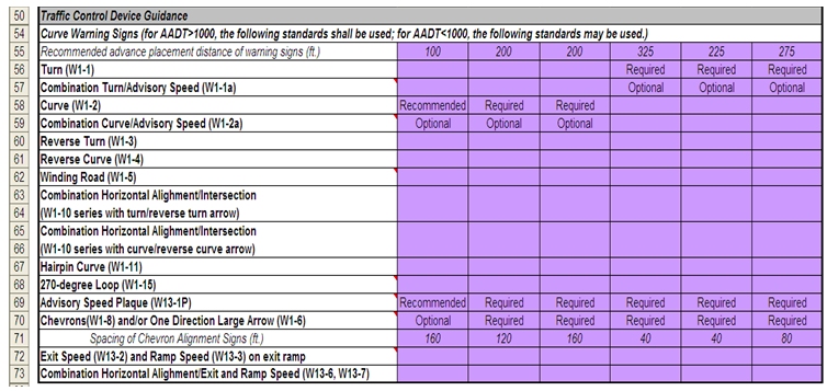
Once the advisory speed and the roadway's posted or statutory speed limit or 85th-percentile speed, whichever is higher, are determined, the appropriate and consistent traffic control devices for the signing of horizontal curves can be determined.
These guidelines were derived from the MUTCD 2009 edition (3) and are intended to complement the procedures for setting advisory speeds on curves. Together, the procedure and guidelines provide a rational basis for establishing uniform signing for horizontal curves. The curve warning sign guidelines have been incorporated into the Curve Advisory Speed (CAS) software and the sign suggestion is automatically displayed once the advisory speed value is determined and the other relevant geometry information is entered.

