U.S. Department of Transportation
Federal Highway Administration
1200 New Jersey Avenue, SE
Washington, DC 20590
202-366-4000

U.S. Department of Transportation
Federal Highway Administration
1200 New Jersey Ave. S.E.
Washington, D.C. 20590
June 5, 2008
In Reply Refer To: HSSD/B-178
Mr. Kevin K. Groeneweg
Mobile Barriers LLC
24918 Genesee Trail Road
Golden, CO 80401
Dear Mr. Groeneweg:
This letter is in response to your request for Federal Highway Administration (FHWA) acceptance of a roadside safety device for use on the National Highway System (NHS).
You requested that we find this device acceptable for use on the NHS under the provisions of National Cooperative Highway Research Program (NCHRP) Report 350 “Recommended Procedures for the Safety Performance Evaluation of Highway Features” and the proposed American Association of State Highway and Transportation Officials’ Manual for Assessing Safety Hardware – 2008 (MASH-08).
Requirements
Roadside safety devices should meet the guidelines contained in the NCHRP Report 350, "Recommended Procedures for the Safety Performance Evaluation of Highway Features". FHWA Memorandum “ACTION: Identifying Acceptable Highway Safety Features” of July 25, 1997, provides further guidance on crash testing requirements of longitudinal barriers. You have also chosen to anticipate the adoption of MASH-08, an option that FHWA has offered with the understanding that additional testing may need to be done if changes to the test criteria are made before MASH-08 is formally adopted.
Description
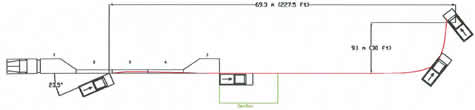
The Mobile Barrier Trailer (MBT) is an integrated, rigid wall, semi-trailer that is used in conjunction with standard semi-tractors to provide mobile, improved, safety, and work environments for personnel at applicable maintenance, construction, and security sites. It is an extended, mobile, longitudinal barrier that provides a physical and visual wall between passing traffic and the maintenance and construction personnel. With an integrated crash attenuator at the rear, a semi-tractor at the front, and a rigid wall on the side toward passing traffic, the MBT will provide approximately 30.5 m (100 ft) of barrier and protected work area.
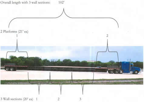
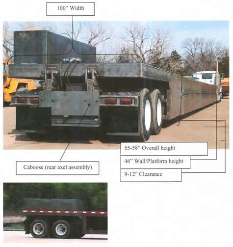
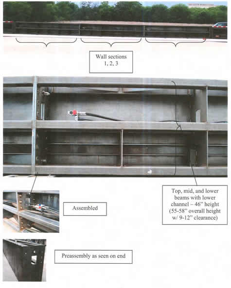
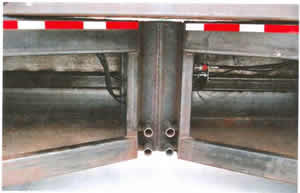
The basic trailer is comprised of two platforms and up to three wall sections. The platforms are each 6.4 m (21 ft) in overall length, 2.54 m (100 in) wide and 1.22 m (4 ft) high (riding approximately 1.52 m (5 ft) high with 305 mm (12 in) of ground clearance). The wall sections are each 6.10 m (20 ft) long, 610 mm (24 in) wide, and 1.22 m (4 ft) high (riding approximately 1.52 m (5 ft) high with 305 mm (12 in) of ground clearance). A homogenous 6.4 mm (0.25 in) steel plate is welded to cover the outer side of each wall section. Each wall section abuts up against another of the platforms and is built the same to take an impact from either direction. There. are no snag points at the seams. The outer 6.4 mm (0.25 in) plate and associated welds are ground beveled to transition from one to the other.
Dimensioned illustrations of the trailer are enclosed for reference as "Appendix A."
Crash Testing
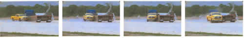
One full-scale crash test was conducted using a 2329 kg Dodge, Ram quad cab pickup truck impacting at 23.5 degrees at 102.3 km/hr. The MBT deflected 0.61m (2 ft) during the jmpact. As seen in the enclosed test data summary sheet the evaluation criteria were within the limits specified in MASH-08.
Findings
Therefore, the-MBT described above and detailed in the enclosed dimensioned photographs is acceptable for use on the NHS under the range of condhions tested, when allowed by a highway agency. It will be acceptable for TL-2 or TL-3 usage depending on the test level of the Truck Mounted Attenuator that is affixed to the rear.
You subsequently requested that FHW A accept the MASH-08 Test 3-11 as indicative of the NCHRP Report 350 acceptance as well. Because the nature of the MBT device and the impact performance of the MASH-08 pickup truck we can conclude that the MASH-08 Test 10 and the NCHRP Report 350 Tests 10 and 11 can be waived. (The MBT is a semi-rigid vertical wall with relatively low friction characteristics that can be favorably compared to vertical concrete barrier walls that passed prior full-scale testing).
Please note the following standard provisions that apply to the FHW A letters of acceptance:
Sincerely yours,
David A. Nicol, P.E. |
(Contents of Appendix A submitted by Mobile Barriers LLC)
Overview
View as assembled with three wall sections
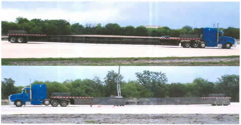
Shortened configuration prepared for transport w/ wall sections atop combined platforms.
| Breakdown: | Platforms and rear axel assembly ("caboose") - 20,000 lbs |
|---|---|
| Wall sections - 5,000 lbs (ea) | |
| Counterweight - 5,000 lbs per wall section | |
| Tractor and accompaniments - 20,000 lbs |
Overview (cont)...
Dimensions...
Dimensions (cont)...
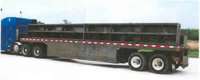
Trailer & Caboose (rear axel assembly) as seen from rear traffic side - wheel cover panel and TMA not shown. (license plate and splashguards blacked out)
Wall construction...
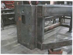
Platform Construction...

Platforms connected and loaded for transport, shown open from work side.
Skeletal view.
 | ||||||||||||||||||||||||||||||||||||||||||||||||||||||||||||||||||||||||||||||||||||||
|---|---|---|---|---|---|---|---|---|---|---|---|---|---|---|---|---|---|---|---|---|---|---|---|---|---|---|---|---|---|---|---|---|---|---|---|---|---|---|---|---|---|---|---|---|---|---|---|---|---|---|---|---|---|---|---|---|---|---|---|---|---|---|---|---|---|---|---|---|---|---|---|---|---|---|---|---|---|---|---|---|---|---|---|---|---|---|
|
|
|
||||||||||||||||||||||||||||||||||||||||||||||||||||||||||||||||||||||||||||||||||||
| ||||||||||||||||||||||||||||||||||||||||||||||||||||||||||||||||||||||||||||||||||||||