Safety Eligibility Letter B-246
Download Version
PDF [2.49 MB]

U.S. Department of Transportation
Federal Highway Administration
1200 New Jersey Ave. S.E.
Washington, D.C. 20590
March 11, 20 14
Reply Refer To: HSST/B-246
Mr. Barry Stephens
Trinity Highway Products, LLC
3617 Cincinnati Avenue
Rocklin, CA. 95765
Dear Mr. Stephens:
This letter is in response to your request for the Federal Highway Administration (FHWA) to
review a roadside safety system for eligibility for reimbursement under the Federal-aid highway
program.
| Name of system: |
Retro-Rail™, MASH |
| Type of system: |
Longitudinal Barrier |
| Test Level: |
AASHTO MASH TL3 |
| Testing conducted by: |
E-Tech Testing Services, Inc. |
| Task Force 13 Designator: |
SGR48 |
| Date of request: |
October 30, 2013 |
| Date of completed package: |
November 30, 2013 |
Decision:
The following device is eligible, with details provided in the form which is attached as an
integral part of this letter:
Based on a review of crash test results you submitted certifying the device described herein
meets the crash test and evaluation criteria of the American Association of State Highway and
Transportation Officials' Manual for Assessing Safety Hardware (MASH), the device is eligible
for reimbursement under the Federal-aid highway program. Eligibility for reimbursement under
the Federal-aid highway program does not establish approval or endorsement by the FHW A for
any particular purpose or use.
The FHWA, the Department of Transportation, and the United States Government do not
endorse products or services and the issuance of a reimbursement eligibility letter is not an
endorsement of any product or service.
Requirements
To be found eligible for Federal-aid funding, roadside safety devices should meet the crash test
and evaluation criteria contained in the American Association of State Highway and
Transportation Officials' Manual for Assessing Safety Hardware (MASH).
Description
The device and supporting documentation are described in the attached form.
Summary and Standard Provisions
Therefore, the system described and detailed in the attached form is eligible for reimbursement and may be installed under the range of conditions tested. Please note the following standard provisions that apply to FHW A eligibility letters:
- This letter provides a AASHTO/ARTBA/AGC Task Force 13 designator that should be used for the purpose of the creation of a new and/or the update of existing Task Force 13 drawing for posting on the on-line 'Guide to Standardized Highway Barrier Hardware' currently referenced in AASHTO Roadside Design Guide.
- This finding of eligibility does not cover other structural features of the systems, nor conformity with the Manual on Uniform Traffic Control Devices.
- Any changes that may influence system conformance with MASH will require a new reimbursement eligibility letter.
- Should the FHW A discover that the qualification testing was flawed, that in-service performance reveals safety problems, or that the system is significantly different from the version that was crash tested, we reserve the right to modify or revoke this letter.
- You are expected to supply potential users with sufficient information on design and installation requirements to ensure proper performance.
- You are expected to certify to potential users that the hardware furnished has the same chemistry, mechanical properties, and geometry as that submitted for review, and that it will meet the test and evaluation criteria of the MASH.
- To prevent misunderstanding by others, this letter of eligibility is designated as number B-246 and shall not be reproduced except in full. This letter and the test documentation upon which it is based are public information. All such letters and documentation may be reviewed at our office upon request.
- This letter shall not be construed as authorization or consent by the FHW A to use, manufacture, or sell any patented system for which the applicant is not the patent holder. The FHW A does not become involved in issues concerning patent law. Patent issues, if any, are to be resolved by the applicant.
- Because it is a steel product. the Retro-Railn1, MASH is subject to Section 635.410 (Buy America) of Title 23. U.S. Code of Federal Regulations, and cannot be permanently incorporated into any federally funded project unless it is made in the
U.S. from U.S. steel.
| |
Sincerely yours,
/* Signature of Michael S. Griffith*/
Michael S. Griffith
Director, Office of Safety Technologies
Office of Safety |
|
Enclosures
Request for Federal Aid Reimbursement Eligibility
Of Highway Safety Hardware
| Submitter |
Date of Request: |
October 30, 2013 |
 New New  Resubmission Resubmission |
| Name: |
Barry Stephens |
Signature: /s/ Barry Stephens |
| Company: |
Trinity Highway Products, LLC |
| Address: |
3617 Cincinnati Ave, Rocklin, CA 95765 |
| Country: |
USA |
| To: |
Michael S. Griffith, Director
FHWA, Office of Safety Technologies |
I request the following devices be considered eligible for reimbursement under the Federal-aid
highway program.
| System Type |
Submission Type |
Device Name/Variant |
Testing Criterion |
Test Level |
| 'B': Barriers (Roadside,
Median, Bridge Railings) |
 Physical Crash Testing Physical Crash Testing
 FEA & V&V Analysis FEA & V&V Analysis |
Retro-Rail™ |
AASHTO MASH |
TL3 |
By submitting this request for review and evaluation by the Federal Highway Administration, I certify that the product(s) was (were) tested in conformity with the AASHTO Manual for Assessing Safety Hardware and that the evaluation results meet the appropriate evaluation criteria in the MASH.
Identification of the individual or organization responsible for the product:
| Contact Name: |
Barry Stephens |
Same as Submitter ☒ |
| Company Name: |
Trinity Highway Products, LLC |
Same as Submitter ☒ |
| Address: |
3617 Cincinnati Ave, Rocklin, CA 95765 |
Same as Submitter ☒ |
| Country: |
USA |
Same as Submitter ☒ |
PRODUCT DESCRIPTION
| New Hardware |
The Retro-Rail™ System has been crash tested and found to successfully meet MASH Test Level3 impact criteria when properly attached to structurally-sound, "Strong-Post" Guardrail, with a rail height of 25" to 29", [Reference- 2009 American Association of State Highway and Transportation Officials (AASHTO) Publication; Manual for Assessing Safety Hardware (MASH)]. Height is measured to the top of the rail from a horizontal tangent projected out from the top of an adjacent roadway. The following types of Strong-Post Guardrail have been evaluated and are deemed suitable for retrofitting with the Retro-Rail™ System:
- SGR04c - Steel Post/ Wood Blockout.
- SGR04b - Wood Post/ Wood Blockout.
- SGR04c - Steel Post/ Plastic or Composite Blockout (Similar to King Block®, width 1 05mm[4.0"] height 355mm [14.0"]), depth 185mm [7.3")).
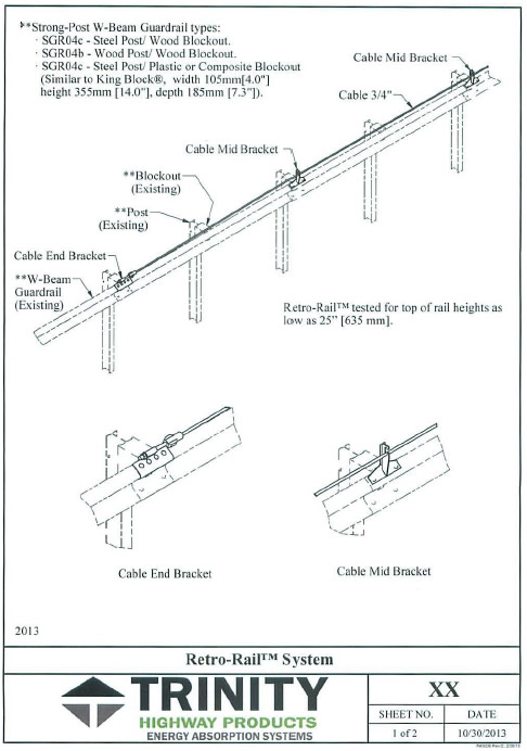
The Retro-Rail™ System consists of two Cable End Brackets, a single 3/4" (19 mm) galvanized wire rope running the length of the installation, and numerous Cable Mid Brackets supporting the wire rope ˜ 6" (1 52 mm) above the top of the rail. Cable Mid Brackets are installed every 12'-6" (1,905 mm), using standard guardrail splice locations. The Cable End Brackets and Mid Brackets maximize use of existing holes in the rail for attachment, minimizing the need to drill additional holes.
The Cable End Bracket consists of inner and outer galvanized components that "sandwich" a guardrail splice at the termination points of the Retro-Rail™. The Cable End Brackets are designed to work with the rail to resist normal and impact Retro-Rail™ Cable tension. The top of the Cable End Brackets are fitted with a steel tube that accommodates the threaded end of the Cable. The Cable End Bracket design is universal, allowing a single component to be installed at either end of the system.
The Cable Mid Brackets incorporate an "engineered cable retention slot" intended to allow the Cable to float freely within the bracket. During Guardrail impacts, the Bracket is designed to bend rearward, which facilitates release of the Cable. This "release" transfers a significant portion of the impact vehicle's lateral impact energy Into the tensioned Retro-Rail™ Cable. The Cable Mid Bracket is designed to maintain standard wire rope tension when installed on guardrail with concave radii of 100' or greater. If the Bracket experiences significant longitudinal loading during Impacts, It is designed to bend and lay flat on top of the rail, reducing vehicle snagging.
The Cable is 3/4" 3 x 7 galvanized wire rope with threaded cable ends. It is pre-stretched at the factory. During the Retro-Rail™ installation, the Cable is tensioned to ˜ 3500 pounds (dependent on the ambient temperature at the time of the installation).
A combined MASH Test Level3 Guardrail Level3 Guardrail & End Terminal system can be created by attaching one of the above NCHRP 350 Retro-Rail™-fitted Strong-Post Guardrails immediately downstream from a MASH, TL-3-accepted End Terminal.
|
Return to top
CRASH TESTING
A brief description of each crash test and its result:
| Required Test Number |
Narrative Description |
Evaluation Results |
| 3-10 (1100C) |
Two MASH 3-10 tests were successfully completed on the Retro-
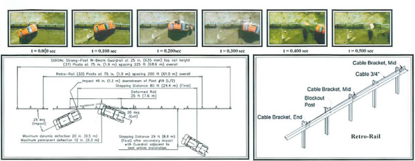
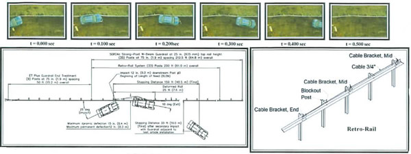
Rail™ System, Test 01-D289-Q02 and 01-Q289-Q04. Both installations used Steel Posts/ Routed Wood Blockouts on 6'-3" centers, 13-½" long 12 Ga W-Beam Guardrail with the top edge 25" above grade and the Retro-Rail™ System attached above and tensioned. Test 01-0289-002 impact occurred 48" downstream of Post #19, L/2. This location was selected because it is believed to be "worst case". Impact would create the greatest snag potential between the post and vehicle and create the greatest likelihood of W-Beam rupture. Test 01-0289-D04 impact occurred 12" downstream of post #3 to establish system Beginning Length of Need (BLON). |
PASS |
| 3-11 (2270P) |
Four MASH 3-11 tests were successfully completed on the Retro-
Rail™ System, Test 01-0289-001 and 01-0289-003 installations used
Steel Posts/ Routed Wood Blockouts on 6'-3" centers, 13'-6½" long
12 Ga W-Beam Guardrail with the top edge 25" above grade and
the Retro-Rail™ System attached above and tensioned. Test
01-0289-001 impact occurred 48" downstream of Post #19, L/2.
This location was selected because it is believed to be "worst case".
Impact would create the greatest snag potential between the post
and vehicle and create the greatest likelihood of W-Beam rupture.
Test 01-0289-003 impact occurred 12" downstream of post #3 to
establish system Beginning Length of Need (BLON). Tests
01-0289-005 and 01-0289-006 were conducted to further evaluate
Post/ Blockout combinations: Wood Post/ Blackout and Steel Post/
Composite Blockout respectively. To create the worst case scenario
for these Post and Blockout combinations, the impact occurred 48"
downstream of Post #19, L/2. This impact would create the greatest
snag potential between the post and vehicle and create the
greatest likelihood of W-Beam rupture.
|
WAIVER REQUEST |
| 3-20 (1100C) |
At this time the intended use of the Retro-Rail™ System is not to
improve impact performance in transitioning from semi-rigid to rigid barrier. Instead, replacement of this transition area may be required to reach acceptable performance levels. The Retro-Rail™
System has been designed to attach to various Transition types and
heights. |
WAIVER REQUESTED |
| 3-21 (2270P) |
See comments above (Required Test Number 3-20 (11 00C) |
WAIVER REQUESTED |
Full Scale Crash Testing was done in compliance with MASH by the following accredited crash test laboratory (cite the laboratory's accreditation status as noted in the crash test reports.):
| Laboratory Name: |
E-Tech Testing Services, Inc. |
| Laboratory Contact: |
John F. LaTurner |
Same as Submitter ☐ |
| Address: |
3617B Cincinnati Ave, Rocklin, CA 95765 |
Same as Submitter ☐ |
| Country: |
USA |
Same as Submitter ☒ |
Accreditation Certificate
Number and Date: |
A2LA, Mechanical #0989.01, November 30, 2013 |
Return to top
ATTACHMENTS
Attach to this form:
- 1) A copy of the full test report, video, and a Test Data Summary Sheet for each test conducted in
support of this request.
- 2) A drawing or drawings of the device(s) that conform to the Task Force-13 Drawing Specifications
[Hardware Guide Drawing Standards]. For proprietary products, a single isometric line drawing is
usually acceptable to illustrate the product, with detailed specifications, intended use, and contact
information provided on the reverse. Additional drawings (not in TF-13 format) showing details that
are key to understanding the performance of the device should also be submitted to facilitate our
review.
FHWA Official Business Only:
| Eligibility Letter |
AASHTO TF13 |
Key Words |
| Number |
Date |
Designator |
| B-246 |
February 18, 2014 |
SGR48 |
MASH TL3, Retrofit Strong-Post Guardrail, Cable End Brackets, Mid Brackets. |
Return to top
Return to top
| General Information |
| Test Agency |
E-TECH Testing Services, Inc |
| Test Designation |
MASH Test 3-10 at L2 |
| Test No. |
01 -0289-002 |
| Date |
10/4/12 |
| Test Article |
| Type |
Retro-Rail System
|
| Installation Length |
SGR04c Guardrai1 225 ft (68.6 m)
overall at 25 in. (635 mm) top height
with 200 ft (61 m) Retro-Rail |
| Material
of key elements |
Retro-Rail Cable ¼ (19 mm) 3 × galvanized, End and Mid Brackets
galvanized steel |
| Foundation and Anchoring |
|
| Test Vehicle |
| Type |
Production Model |
| Designation |
1100C |
| Model |
2004 Kia Rio |
| Mass |
| Curb |
2354 lb (1068 kg) |
| Test inertial |
2414 lb (1095) kg |
| Dummy |
N/A |
| Gross Static |
2414 lb (1095) kg |
| Impact Conditions |
| Speed (km/h)e |
63.9 mi/h (102.9 km/h) |
| Angle (deg) |
25 |
| Impact Severity (kJ)e |
58.9 ft-kip (79.8 KJ) |
|
| Exit conditions |
| Speed (km/h) |
33.6 mi/h (54 km/h) |
| Angle (deg - veh. e.g.) |
20 |
| Occupant Risk Values |
| Impact Velocity (m/s) |
| x-direction |
19.2 ft/s (5.8 m/s) |
| y-direction |
23.0 ft/s (7.0 m/s) |
| Ridedown Acceleration (g's) |
| x-direction |
12.0 |
| y-direction |
9.6 |
| European Committee for Normalization (CEN) Values |
| THIV |
19.6 mi/h (31.5 km/h) |
| PHD (g's) |
14.0 |
| ASI |
1.2 |
| Post-Impact Vehicular Behavior (deg - rate gyro) |
| Maximum Roll Angle |
8.1 |
| Maximum Pitch Angle |
-4.1 |
| Maximum Yaw Angle |
-80.5 |
Test Article Deflections (m)
Dynamic
Permanent |
20 in. (0.5 m)
12 in. (0.3 m)
|
| Vehicle Damage (Primary Impact)
Exterior |
| VDS |
LFQ03 |
| CDC |
HLFEW3 |
| Interior |
| VCDI |
NS0000000 |
| Maximum Deformation |
Negligible |
|
Figure 1. Summary of Results - Retro-Rail Test 01-0289-002
| General Information |
| Test Agency |
E-TECH Testing Services, Inc |
| Test Designation |
NCHRP 350 Test 3-30 at BLON |
| Test No. |
01-0289-004 |
| Date |
01-09-13 |
| Test Article |
| Type |
Trinity Highway Products, LLC
Retro-Rail System |
| Installation Length |
SGR04c Guardrail 212.5 ft (64.8 m)
overall at 25 in. (635 mm) top height
with 200 ft (661.0 m) Retro-Rail and
50 ft (15.2 m) upstream ET Plus End
Terminal anchor. |
| Material
of key elements |
Retro-Rail Cable ¾ in. (19 mm) 3 × 7 galvanized, End and Mid
Brackets galvanized steel |
| Foundation and Anchoring |
AASHTO Strong Soil, compacted and
well drained |
| Test Vehicle |
| Type |
Production Model |
| Designation |
1100C |
| Model |
2500 Kia Rio |
| Mass (kg) |
| Curb |
2351 lb (1066.5 kg) |
| Test inertial |
2399 lb (1088 kg) |
| Dummy |
7165 lb (5 kg) |
| Gross Static |
1994 |
| Impact Conditions |
| Speed (km/h)e |
60.0 mi/h (96.5 km/h) |
| Angle (deg) |
25 |
| Impact Severity |
51.5 ft-kip (69.8 kJ) |
|
| Exit conditions |
| Speed (km/h) |
44.7 mi/h (72 km/h) |
| Angle (deg) |
10 |
| Occupant Risk Values |
| Impact Velocity (m/s) |
| x-direction |
13.3 ft/s (4.0 m/s) |
| y-direction |
22.2 ft/s 6.8 m/s) |
| Ridedown Acceleration (g's) |
| x-direction |
6.2 |
| y-direction |
9.3 |
| European Committee for Normalization (CEN) Values |
| THIV |
17.6 mi/h (28.4 km/h) |
| PHD (g's) |
10.6 |
| ASI |
1.2 |
| Post-Impact Vehicular Behavior (deg - rate gyro) |
| Maximum Roll Angle |
-3.3 |
| Maximum Pitch Angle |
3.1 |
| Maximum Yaw Angle |
36.9 |
Test Article Deflections (m)
Dynamic
Permanent |
15 in. (0.4 m)
12 in. (0.3 m) |
Vehicle Damage (Primary Impact)
Exterior |
| VDC |
LFQ-3 |
| CDC |
11LFEW3 |
| Interior |
| VCDI |
NS0000000 |
| Maximum Deformation (mm) |
Negligible |
|
Figure 6. Summary Results - Retro-Rail Test 0l-0289-004
Return to top
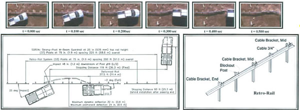
| General Information |
| Test Agency |
E-TECH Testing Services, Inc |
| Test Designation |
MASH Test 3-11 at L/2 |
| Test No. |
01-0289-001 |
| Date |
09-21-12 |
| Test Article |
| Type |
Trinity Highway Products, LLC
Retro-Rail System |
| Installation Length |
SGR04c Guardrail 225 ft (68.6 m)
overall at 25 in. (635 mm) top height
with 200 ft (61.0 m) Retro-Rail, |
| Material
of key elements |
Retro-Rail Cable ¾ in. (19 mm) 3 × 7 galvanized, End and Mid
Brackets galvanized steel |
| Foundation and Anchoring |
AASHTO Strong Soil, compacted and
well drained |
| Test Vehicle |
| Type |
Production Model |
| Designation |
2270P |
| Model |
2006 Dodge Ram Pickup |
| Mass (kg) |
| Curb |
5046 lb (2289 kg) |
| Test inertial |
4996 lb (2266 kg) |
| Dummy |
N/A |
| Gross Static |
4496 lb (2266 kg) |
| Impact Conditions |
| Speed (km/h)e |
61.3 mi/h (98.8 km/h) |
| Angle (deg) |
25 |
| Impact Severity |
112.0 ft-kip (151.9 kJ) |
|
| Exit conditions |
| Speed (km/h) |
42.3 mi/h (68 km/h) |
| Angle (deg) |
-2 |
| Occupant Risk Values |
| Impact Velocity (m/s) |
| x-direction |
15.6 ft/s (4.7 m/s) |
| y-direction |
15.7 ft/s (48 m/s) |
| Ridedown Acceleration (g's) |
| x-direction |
8.1 |
| y-direction |
6.5 |
| European Committee for Normalization (CEN) Values |
| THIV |
14.2 mi/h (22.9 km/h) |
| PHD (g's) |
10.2 |
| ASI |
0.6 |
| Post-Impact Vehicular Behavior (deg - rate gyro) |
| Maximum Roll Angle |
31.3 |
| Maximum Pitch Angle |
-6.7 |
| Maximum Yaw Angle |
-29.9 |
Test Article Deflections (m)
Dynamic
Permanent |
43 in. (1.1 m)
30 in. (0.8 m) |
Vehicle Damage (Primary Impact)
Exterior |
| VDC |
LFQ-2 |
| CDC |
11LFEW2 |
| Interior |
| VCDI |
NS0000000 |
| Maximum Deformation (mm) |
Negligible |
|
| General Information |
| Test Agency |
E-TECH Testing Services, Inc |
| Test Designation |
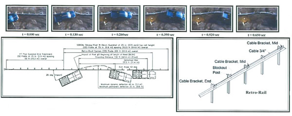
MASH Test 3-11 at BLON |
| Test No. |
01-0289-003 |
| Date |
12-11-12 |
| Test Article |
| Type |
Trinity Highway Products, LLC
Retro-Rail System |
| Installation Length |
SGR04c Guardrail 212.5 ft (64.8 m)
overall at 25 in. (635 mm) top height
with 200 ft (61.0 m) Retro-Rail, |
| Material
of key elements |
Retro-Rail Cable ¾ in. (19 mm) 3 × 7 galvanized, End and Mid
Brackets galvanized steel |
| Foundation and Anchoring |
AASHTO Strong Soil, compacted and
well drained |
| Test Vehicle |
| Type |
Production Model |
| Designation |
2270P |
| Model |
2006 Dodge Ram Pickup |
| Mass (kg) |
| Curb |
5046 lb (2289 kg) |
| Test inertial |
4996 lb (2266 kg) |
| Dummy |
N/A |
| Gross Static |
4496 lb (2266 kg) |
| Impact Conditions |
| Speed (km/h)e |
61.3 mi/h (98.8 km/h) |
| Angle (deg) |
25 |
| Impact Severity |
112.0 ft-kip (151.9 kJ) |
|
| Exit conditions |
| Speed (km/h) |
42.3 mi/h (68 km/h) |
| Angle (deg) |
-2 |
| Occupant Risk Values |
|
| Impact Velocity (m/s) |
| x-direction |
15.6 ft/s (4.7 m/s) |
| y-direction |
15.7 ft/s (48 m/s) |
| Ridedown Acceleration (g's) |
| x-direction |
8.1 |
| y-direction |
6.5 |
| European Committee for Normalization (CEN) Values |
|
| THIV |
14.2 mi/h (22.9 km/h) |
| PHD (g's) |
10.2 |
| ASI |
0.6 |
| Post-Impact Vehicular Behavior (deg - rate gyro) |
|
| Maximum Roll Angle |
31.3 |
| Maximum Pitch Angle |
-6.7 |
| Maximum Yaw Angle |
-29.9 |
Test Article Deflections (m)
Dynamic
Permanent |
43 in. (1.1 m)
30 in. (0.8 m) |
Vehicle Damage (Primary Impact)
Exterior |
| VDC |
LFQ-2 |
| CDC |
11LFEW2 |
| Interior |
| VCDI |
NS0000000 |
| Maximum Deformation (mm) |
Negligible |
|
Figure 16. Summary of Results- Retro-Rail Test 01-0289-003
| General Information |
| Test Agency |
E-TECH Testing Services, Inc |
| Test Designation |
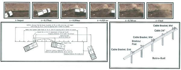
MASH Test 3-11 |
| Test No. |
01-0289-005 |
| Date |
7/24/13 |
| Test Article |
| Type |
Trinity Highway Products, LLC
Retro-Rail System |
| Installation Length |
SGR04c Guardrail 225 ft (68.6 m)
overall at 25 in. (635 mm) top height
with 200 ft (61.0 m) Retro-Rail, |
| Material
of key elements |
Retro-Rail Cable ¾ in. (19 mm) 3 × 7 galvanized, End and Mid
Brackets galvanized steel |
| Foundation and Anchoring |
AASHTO Strong Soil, compacted and
well drained |
| Test Vehicle |
| Type |
Production Model |
| Designation |
2270P |
| Model |
2007 Chevrolet Pickup |
| Mass (kg) |
| Curb |
5337 lb (2241 kg) |
| Test inertial |
5062 lb (2296 kg) |
| Dummy |
N/A |
| Gross Static |
5062 lb (2296 kg) |
| Impact Conditions |
| Speed (km/h)e |
61.2 mi/h (98.5 km/h) |
| Angle (deg) |
25 |
| Impact Severity |
113.1 ft-kip (153.4 kJ) |
|
| Exit conditions |
| Speed (km/h) |
49.1 mi/h (79.0 km/h) |
| Angle (deg) |
4 |
| Occupant Risk Values |
|
| Impact Velocity (m/s) |
| x-direction |
8.5 ft/s (2.6 m/s) |
| y-direction |
11.3 ft/s (3.4 m/s) |
| Ridedown Acceleration (g's) |
| x-direction |
5.1 |
| y-direction |
3.6 |
| European Committee for Normalization (EN) Values |
| THIV |
9.4 mi/h (15.2 km/h) |
| PHD (g's) |
5.1 |
| ASI |
0.4 |
| Post-Impact Vehicular Behavior (deg - rate gyro) |
|
| Maximum Roll Angle |
28.1 |
| Maximum Pitch Angle |
-8.2 |
| Maximum Yaw Angle |
111.9 |
Test Article Deflections (m)
Dynamic
Permanent |
67 in. (1.7 m)
35 in. (0.9 m) |
Vehicle Damage (Primary Impact)
Exterior |
| VDC |
LFQ-3 |
| CDC |
11LFEW3 |
| Interior |
| VCDI |
NS0000000 |
| Maximum Deformation (mm) |
Negligible |
|
Figure 21. Summary of Results - Retro-Rail Test 01-0289-005
| General Information |
| Test Agency |
E-TECH Testing Services, Inc |
| Test Designation |
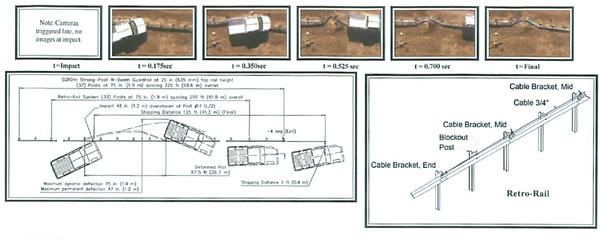
MASH Test 3-11 |
| Test No. |
01-0289-006 |
| Date |
08/16/13 |
| Test Article |
| Type |
Trinity Highway Products, LLC
Retro-Rail System |
| Installation Length |
SGR04c Guardrail 225 ft (68.6 m)
overall at 25 in. (635 mm) top height
with 200 ft (61.0 m) Retro-Rail, |
| Material
of key elements |
Retro-Rail Cable ¾ in. (19 mm) 3 × 7 galvanized, End and Mid
Brackets galvanized steel |
| Foundation and Anchoring |
AASHTO Strong Soil, compacted and
well drained |
| Test Vehicle |
| Type |
Production Model |
| Designation |
2270P |
| Model |
2007 Chevrolet Pickup |
| Mass (kg) |
| Curb |
5337 lb (2241 kg) |
| Test inertial |
5062 lb (2296 kg) |
| Dummy |
N/A |
| Gross Static |
5062 lb (2296 kg) |
| Impact Conditions |
| Speed (km/h)e |
61.2 mi/h (98.5 km/h) |
| Angle (deg) |
25 |
| Impact Severity |
113.1 ft-kip (153.4 kJ) |
|
| Exit conditions |
| Speed (km/h) |
1.9 mi/h (3.0 km/h) |
| Angle (deg) |
-4 |
| Occupant Risk Values |
| Impact Velocity (m/s) |
| x-direction |
17.2 ft/s (5.3 m/s) |
| y-direction |
12.8 ft/s (3.9 m/s) |
| Ridedown Acceleration (g's) |
| x-direction |
9.6 |
| y-direction |
8.4 |
| European Committee for Normalization (EN) Values |
| THIV |
14.1 mi/h (22.7 km/h) |
| PHD (g's) |
12.6 |
| ASI |
0.7 |
| Post-Impact Vehicular Behavior (deg - rate gyro) |
| Maximum Roll Angle |
36,4 |
| Maximum Pitch Angle |
9.0 |
| Maximum Yaw Angle |
28.3 |
| Test Article Deflections (m) |
Dynamic
Permanent |
75 in. (1.9 m)
47 in. (1.2 m) |
Vehicle Damage (Primary Impact)
Exterior |
| VDC |
LFQ-3 |
| CDC |
11LFEW3 |
| Interior |
| VCDI |
NS0000000 |
| Maximum Deformation (mm) |
Negligible |
|
Figure 26. Summary of Results- Retro-Rail Test 01-0289-006


