U.S. Department of Transportation
Federal Highway Administration
1200 New Jersey Avenue, SE
Washington, DC 20590
202-366-4000
![]()
U.S. Department of Transportation
Federal Highway Administration
1200 New Jersey Ave. S.E.
Washington, D.C. 20590
September 9, 2010
In Reply Refer To:
HSSD/B-82D
Mr. Mark Tonks
Group Managing Director
Hill & Smith Limited
Springvale Business & Industrial Park
Billson, Wolverhampton, West Midlands
WV14 0QL United Kingdom
Dear Mr. Tonks:
This letter is in response to your request for the Federal Highway Administration (FHWA) acceptance of a roadside safety system for use on the National Highway System (NHS).
Name of system: Brifen Wire Rope Safety Fence Type of system: High Tension Cable Barrier Test Level: NCHRP Report 350 TL-4 Testing conducted by: SouthWest Research Institute Task Force 13 Designator: PENDING Date of request: May 13, 2010 Date initially acknowledged: May 18, 2010 Date of completed package: June 1, 2010
You requested that we find this system acceptable for use on the NHS under the provisions of the National Cooperative Highway Research Program (NCHRP) Report 350 “Recommended Procedures for the Safety Performance Evaluation of Highway Features.”
Requirements
Roadside safety devices should meet the guidelines contained in the NCHRP Report 350 or the American Association of State Highway and Transportation Officials‘ Manual for Assessing Safety Hardware. The FHWA memorandum “Identifying Acceptable Highway Safety Features” of July 25, 1997, provides further guidance on crash testing requirements of longitudinal barriers.
Description
On May 19, 2010, you and your representative, Dr. Richard McGinnis, met with Mr. Artimovich of my staff and provided him with a copy of a test report prepared by the Southwest Research Institute (SwRI) entitled "NCHRP Report 350, Test 3-11 Full-Scale Crash Evaluation of a Brifen® Wire Rope Safety Fence (WRSF) (Deflection Test), SwRI Test Number B-2." This report detailed a test conducted by personnel from the SwRI at a temporary site in Ardmore, Oklahoma. The 60-meter (197-foot) long test article was a standard 4-cable Brifen® WRSF with cable heights of 36.5 in (930 mm), 30.5 in (770 mm), 24.5 in (620 mm), and 18.5 in (470 mm). The 21-ft (6.4-m) spaced posts were 4 in (100 mm) by 2-3/16 in (55 mm) by 0.1793 in (4.5 mm) in cross-section and were placed in steel sockets embedded in concrete foundations. This system is identical to the Brifen Test level 4 (TL-4) system described in FHWA acceptance letter B-82B dated March 27, 2005, except for the post spacing and the three lower cables are each 0.4 in (10 mm) lower than the original design. The difference in the cable heights is within the allowable construction tolerance. The purpose of this test was to ascertain the dynamic deflection of a Brifen installation with 21-ft (6.4-m) post spacing.
Crash Testing
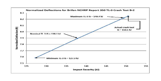
When impacted at 24.7 degrees and 101.2 km/h with a 2182-kg pickup truck, the dynamic deflection of the safety fence installation was reported to be 2.5 meters (8.25 feet). All NCHRP Report 350 evaluation criteria for this test were satisfactorily met. You indicate in your letter that the impact severity of the crash was computed to be 150.5 kJ which is 9 percent higher than the target value of 138.1 kJ for NCHRP Report 350 TL-3 crash tests. Further we note that you used a European Union equation to normalize the dynamic deflection and estimated that the deflection would have been approximately 7.9 ft had the impact severity been the standard NCHRP Report 350 TL-3 value of 138.1 kJ. The figure below shows the actual and normalized deflections for NCHRP Report 350 TL-3 impact severities (minimum, nominal, and maximum). As we have stated in earlier acceptance letters for cable barriers, the design deflection distance is based on a single standard test conducted under carefully controlled conditions. It should not be considered an exact distance, but rather as a single point within the range of deflections that can be expected under actual field conditions.
In the crash test rigging screws were purposely arranged so that they would be located in the area where vehicle-barrier contact occurs to demonstrate that their location does not affect barrier performance. Two rigging screws were located at post 9, and the other two rigging screws were located midspan between posts 8 and 9. The vehicle was in contact with the barrier from post 5 through post 10, inclusive. None of the rigging screws was damaged, and the performance of the barrier was not affected by the rigging screws.
Findings
In summary, based on the most recent crash test your Brifen 4-cable WRSF, remains acceptable as TL-3 and TL-4 traffic barriers and may be used on the NHS with any post spacing from 1.6m (5.2 ft) to 6.4m (21 ft) using driven posts, posts set in driven steel sleeves, or posts in socketed concrete foundations and with 4 cables as long as cable heights and other conditions are consistent with previous FHWA acceptance letters and when such use is specified by the contracting agency. As noted earlier in this letter, the purpose of the referenced crash test was to ascertain the dynamic deflection of a Brifen installation with 21-ft (6.4-m) post spacing. We concur that this design deflection is 7.9 feet.
We understand that all steel components used in any of the accepted Brifen systems are manufactured in the U.S. with U.S. steel and are not subject to the Buy America provisions of Title 23, U.S. Code (USC), Section 635.410.
Although the barrier performed well under ideal test impact conditions, the likelihood of passenger car underrides of any cable system may increase as the post spacing increases, particularly when the barrier is installed on non-level or slightly irregular terrain and the cables are not restrained from lifting at each post. Consequently, some transportation agencies have limited post spacing to approximately 6m (20 feet) for cable barriers. The dynamic deflection of the barrier is likely to increase when it is installed along the convex sides of horizontal curves, and when distances between anchorages exceed the 60-m (200-foot) test length.
Please note the following standard provisions that apply to FHWA letters of acceptance:
Sincerely yours, /* Signature of David A. Nicol */ David A. Nicol, P.E. |
Enclosures
FHWA:HSSD:NArtimovich:tb:61331:8/23/10
File: s://directory folder/nartimovich/B82_DBrifen_21_foot_spacing_fin.doc
cc: HSSD (Reader, HSA; Chron File, HSSD; NArtimovich, HSSD)

