U.S. Department of Transportation
Federal Highway Administration
1200 New Jersey Avenue, SE
Washington, DC 20590
202-366-4000

U.S. Department of Transportation
Federal Highway Administration
1200 New Jersey Ave. S.E.
Washington, D.C. 20590
November 1, 2004
Reply Refer To: HSA-10/CC-35G
Barry D. Stephens, P.E.
November 1, 2004
Senior Vice President of Engineering
Energy Absorption Systems, Incorporated
3 617 Cincinnati A venue
Rocklin, California 95765
Dear Mr. Stephens:
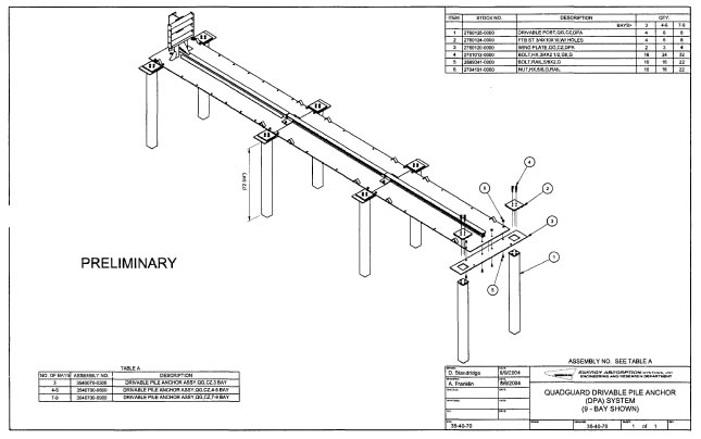
In my December 10, 2003 letter to you, the Federal Highway Administration accepted a modified design for your QuadGuard CZ in which the unit was mounted on a 42-inch wide steel plate anchored to the ground. In your recent October 1, 2004, letter, you requested formal acceptance of a new method for anchoring the steel plate to the ground which eliminates the need for a concrete or asphalt pad, thus making the attenuator easier to install for temporary use in many work zones. The new anchoring system, named the Drivable Pile Anchor (DP A) System and shown in Enclosure I ,consists of a set of steel wing plates (9.5-mm thick × 304-mm wide × 1791-mm long) bolted underneath the QuadGuard base plate and pinned to the ground with 152 mm × 152 mm × 6.35 mm square steel tubes driven 1848 mm deep into a strong soil through square holes in each wing plate. These steel tubes are then capped with a 254 mm × 254 mm × 19 mm steel plate using four 19 mm Grade 8 bolts.
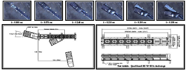
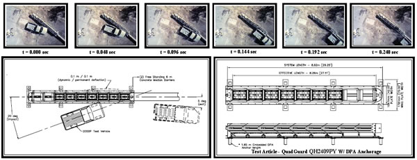
To verify acceptable crash performance of the DP A System, E-TECH Testing Services, Inc. conducted the two National Cooperative Highway Research Program (NCHRP) Report 350 tests that members of my staff had previously agreed would likely place the greatest loading on the anchoring system. In both instances, the QuadGuard performed as it had in previous tests when mounted to a concrete or asphalt pad and neither the steel base plate nor the wing plates showed any significant displacement. The summary results oftest 3-33 and 3-38 are attached as Enclosures 2A and 2B, respectively. Since the new anchorage system was being tested rather than the QuadGuard itself, the failure of the data recording devices in test 3-38 does not invalidate the test because that test was successfully completed earlier with a permanently installed QuadGuard and vehicle crash and post-crash behavior was similar in both tests. I also noted that both new tests were conducted into a 9-bay unit at speeds of 113 km/h, over and above the standard test level 3 (TL-3) speed of 100 km/h.
Based on the information you provided, I agree that any of the previously accepted Quad Guard CZ configurations mounted on a steel plate bolted to a concrete or asphalt pad may also be anchored directly over a strong soil using the DP A anchoring system as described above and as shown on the attached drawing. Both the NCHRP Report 350 test level and the number of wing plates required will depend on the number of bays used at a specific site, with a minimum of two wing plates needed for a 3-bay TL-2 design.
Sincerely yours, /* Signature of John R. Baxter.*/
|
|||
Enclosures

|
|
|||||||||||||||||||||||||||||||||||||||||||||||||||||||||||||||||||||||||||||||||||||||||||
Figure 1. Summary of Results – QuadGuard QH2409PY Test 01-5500-007
The results of this report relate only to the QuadGuard QH2409PY configuration tested. This report may not be reproduced except in full, without the prior written approval of E-TECH Testing Services, Inc.
Prepared by: John F. LaTurner, P.E. – Manager. Report 238 – Issued 8/09/2004
|
|
||||||||||||||||||||||||||||||||||||||||||||||||||||||||||||||||||||||||||||||||||||||||||||||
Figure 1. Summary of Results – QuadGuard QH2409PY Test 01-5500-008
The results of this report relate only to the QuadGuard QH2409PY configuration tested. This report may not be reproduced except in full, without the prior written approval of E-TECH Testing Services, Inc.
Prepared by: John F. LaTurner, P.E. – Manager. Report 240 –
Issued 9/28/2004

