U.S. Department of Transportation
Federal Highway Administration
1200 New Jersey Avenue, SE
Washington, DC 20590
202-366-4000
This brief provides general guidelines regarding the selection, installation, and maintenance of W-beam guardrail terminals. In addition, common issues of concern are identified for these elements with generally accepted practices to address these issues. The American Association of State Highway and Transportation Officials (AASHTO) Roadside Design Guide 4th Edition Chapter 8.3 provides additional guidance on terminal design concepts.
There a re three primary W-beam guardrail end terminal designs in use at present: Burke-in-backslope, non-energy-absorbing, and energy-absorbing. Figure 1 shows th e relative trajectories of a vehicle impacting non-energy-absorbing and energy-absorbing terminals head-on and at high speed (62 mph). The decision to use either an energy-absorbing terminal or a non-energy-absorbing terminal should be based on the likelihood of a near end-on impact and th e nature of the recovery area immediately behind and beyond the terminal.
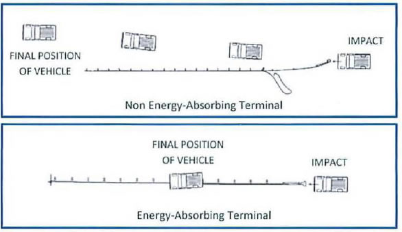
Figure 1: Vehicle Trajectories by Terminal Type
Non Energy-absorbing – A terminal that does not dissipate a significant amount of kinetic energy in a head-on crash and is a gating system that allows the vehicle to traverse the area behind and parallel to the guardrail. Some key characteristics include:
Energy-absorbing - A terminal that dissipates a significant amount of kinetic energy in a head on crash. Some key characteristics include:
Buried-in-Backslope – A terminal that terminates a W-beam guardrail installation by burying the end in the backslope. Grading is critical for a buried-in-backslope terminal because the terrain leading up to the buried-in-backslope must be traversable and contain no fixed object hazards. If the backs lope is relatively flat, a vehicle can ride up the slope and bypass the terminal. When th is condition exists at a site, the designer must ensure that the hazard remains shielded by assessing the available clear run out distance behind the rail and the barrier length-of-need. Also, there are other "grading" design considerations to follow:
Figure 2 is a suggested flowchart that can be used by a designer to select the most appropriate terminal for a specific location. It's important to note that the starting point is to verify that a barrier is actually needed. If so, t hen the correct length of need should be confirmed. If a total length of barrier is less than about 150 feet, an energy-absorbing terminal should be selected for the reason previously stated. When an appropriate backslope exists near the end of the barrier. the buried-in-backslope terminal should be considered. When no suitable backslope exists, either a non-energy-absorbing or energy-absorbing may be appropriate.
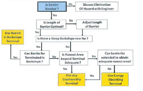
Figure 2: Terminal Selection Flow Chart
Terminal Selection: Common Issues of Concern and Current Generally Accepted Practices.
| Common Issue of Concern | Current General Accepted Practice |
|---|---|
Side-by-side Terminals: |
Bullnose Guardrail System for Median Applications |
| Common Issue of Concern | Current General Accepted Practice |
|---|---|
Curbs |
Curb-Guardrail Refer to NCHRP Report 537 Recommended Guidelines avoided or minimized if for Curb and Curb-Barrier Installations. There are tested curb and guardrail and end terminal combinations covered. |
| Common Issue of Concern | Current General Accepted Practice |
|---|---|
Inadequate Length of Need (LON) |
Extending the barrier or a buried-in-backslope to appropriately shield the hazard. |
| Common Issue of Concern | Current General Accepted Practice |
|---|---|
Terminal flare rate can be excessive on a flared terminal. |
A gating terminal may be considered here because of existing run out area. |
Terminal Installation:
When installing the terminal, the manufacturer's installation manual should be followed closely. Additionally, grading in the area of the terminal is important because terminals are tested for crashworthiness on flat and unobstructed terrain. As shown in Figure 3, there are three grading locations of concern around barrier terminals:
All of these areas should be carefully considered during the design phase or a project. Engineered earthwork and specification of a platform* should also be considered to achieve successful terminal performance. In addition, necessary earthwork should be completed prior to the installation of the safety feature.
*A platform is the required grading for both adjacent & advance areas to acceptable criteria per the Roadside Design Guide.
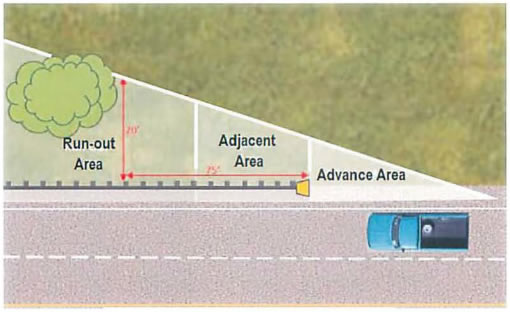
Figure 3: Terminal Grading Areas
| Common Issue of Concern | Current General Accepted Practice |
|---|---|
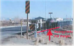
 The "grading platform" in the photo has a drop-off that creates a significantly greater hazard than previously existed. Advance Area: |
Before selecting a grading platform, the designer should first consider the following:
|
Terminal Installation: Common Issues of Concern and Current Generally Accepted Practice
| Common Issue of Concern | Current General Accepted Practice |
|---|---|
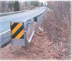
Adjacent Area:When the area immediately behind a terminal (i.e., the "adjacent area") is steep or non-traversable, at vehicle can overturn after breaking through the terminal. A minimum traversable area behind the terminal is an essential part good barrier design. |
A field check should be made to determine
if a run-out area exists. A run-out area
requires the following:
|
| Common Issue of Concern | Current General Accepted Practice |
|---|---|
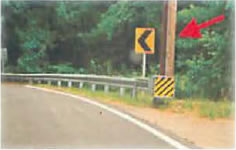
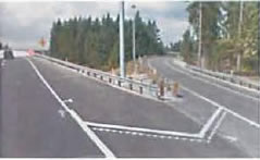
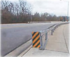
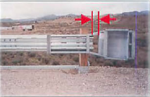
Adjacent Area |
In many situations, it simply may not be practical to shield every hazard. This barrier was installed primarily to shield the slope along the curve and is effective for that purpose, but it should have been lengthened if practical,to shield the pole also. An energy-absorbing terminal can slow a vehicle in line with the rail and is preferable here rather than a non-energy absorbing design. |
| Common Issue of Concern | Current General Accepted Practice |
|---|---|
Advance & Adjacent Area: |
To achieve successful terminal performance, the designer should consider including engineered earthwork as a key component on the final construction plan for the terminal installation. |
| Common Issue of Concern | Current General Accepted Practice |
|---|---|
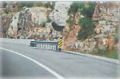
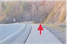
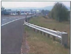
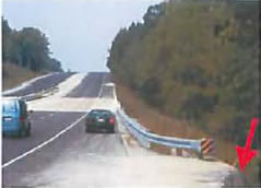
The installation shown here is an energy-absorbing design, so vehicle impacting head-on would likely be stopped safely before reaching the concrete barrier. However, any angled hits at the end would result in significant intrusion behind the rail and into the rock outcropping. |
The guardrail should have been extended to shield the secondary hazard (i.e., the rock wall). A good field check to determine if shielding secondary hazards may be worthwhile is to note whether or not the area immediately upstream from the terminal would warrant shielding in the absence of a primary hazard (i.e., end of the bridge barrier). |
The Roadside Design Guide identifies maintenance factors grouped into three categories: (1) routine maintenance, (2) Crash Maintenance, and (3) material and storage requirements. Common examples of routine maintenance and material and storage requirements are listed below. Routine maintenance includes inspecting roadside devices at regular intervals to determine the condition of the device and required repair needed for the device. Proper materials and storage of them ensures routine maintenance is carried out appropriately using proper components when completing repairs.
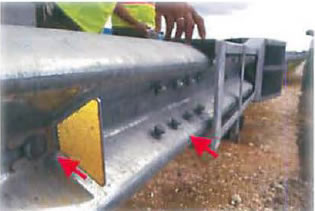
Extruder Heads |
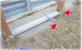
Cable attachments |
Cable anchorage |
|
Mismatched Parts |
In efforts to effectively address the highlighted concerns, the following existing resources and noteworthy practices are provided for consideration by State Departments of Transportation and other highway agencies.
Inspector /Maintenance & Designer Mentoring Training
State and local agencies should conduct training at regular intervals for DOT personnel, consultants,
and contractors to ensure the optimal barrier design and installation of new roadside safety devices,
and the inspection and maintenance of existing devices. This noteworthy practice would serve to
eliminate common installation and maintenance errors that adversely affect the intended
performance of the roadside safety device.
Installer Certification
Installer Certification is training for the roadside safety system installers that may be offered at
regular intervals to maintain a specific knowledge base of both existing and new systems. Agencies
that offer this training may also make this a requirement for installation of roadside safety systems in
their jurisdiction. This noteworthy practice also may serve to eliminate common installation errors
that may adversely affect the intended performance of the roadside safety device.
Engineered earthwork design in construction plans
Crash testing for end treatments is performed on flat or near flat terrain. In real world applications,
this type of terrain is fairly rare and some grading is likely needed. Therefore, end treatments may
require individual construction details and cross sections with regard to earthwork analysis. If this
information is not included in the plan, the end treatment may not fit or function as intended when
installed in the field. In some cases, improperly installed end treatments can degrade the strength or
performance of an entire barrier system.
When roadside safety systems such as traffic barriers and terminals are installed exactly as shown on project plans or replaced in-kind after a crash, the end result can be an installation that may not effectively shield the primary hazard, may be too short or too long, may not shield obvious "secondary" hazards in its immediate vicinity, or may not be needed at all. A per-installation review checklist can be used to recognize field adjustments to a design that are needed to ensure an optimal installation.