U.S. Department of Transportation
Federal Highway Administration
1200 New Jersey Avenue, SE
Washington, DC 20590
202-366-4000
![]()

This document is disseminated under the sponsorship of the U.S. Department of Transportation in the interest of information exchange. The U.S. Government assumes no liability for the use of the information contained in this document. This report does not constitute a standard, specification, or regulation.
The U.S. Government does not endorse products or manufacturers. Trademarks or manufacturers' names appear in this report only because they are considered essential to the objective of this document.
1. Report No. FHWA FHWA-SA-14-071 |
2. Government Accession No. |
3. Recipient's Catalog No. |
|||
4. Title and Subtitle Road Safety Audit Case Studies: Using IHSDM in the RSA Process |
5. Report Date July 2014 |
||||
6. Performing Organization Code |
|||||
7. Authors Dan Nabors, Elissa Goughnour |
8. Performing Organization Report No. |
||||
9. Performing Organization Name and Address Vanasse Hangen Brustlin, Inc. |
10. Work Unit No. (TRAIS) |
||||
11. Contract or Grant No. |
|||||
12. Sponsoring Agency Name and Address Federal Highway Administration |
13. Type of Report and Period Covered Final Report, July 2014 |
||||
14. Sponsoring Agency Code
|
|||||
15. Supplementary Notes: The Federal highway Administration Office of Safety sponsored the study of the Road Safety Audits reported in this document. The Task Manager for this report was Rebecca Crowe (FHWA Office of Safety). Graphic design was provided by Jorge Quinones. |
|||||
16. Abstract Road Safety Audits (RSAs) are a formal safety performance examination of an existing or future roadway or off-road facility and are conducted by an independent, experienced, multidisciplinary team. The purpose of the Road Safety Audit Case Studies: Using IHSDM in the RSA Process is to help Federal, State, Tribal, and local agencies understand the benefits of using the Interactive Highway Safety Design Model (IHSDM) during the RSA process as a decision-support tool to evaluate and estimate the safety and operation of various design features. This case study document provides a review of the RSA process, an overview of IHSDM, and three case study examples of RSAs that utilized IHSDM. The case studies include photographs, a project background, how IHSDM was used, key RSA findings and suggestions, and the benefits of the IHSDM. These case studies will help jurisdictions incorporate this useful decision-support tool into the RSA process. |
|||||
17. Key Words Road safety audit, Interactive Highway Safety Design Model, IHSDM, decision-support tool, roadway design |
18. Distribution Statement No restrictions. This document is available to the public through the National Technical Information Service, Springfield, Virginia 22161. |
||||
19. Security Classif. (of this report) Unclassified |
20. Security Classif. (of this page) Unclassified |
21. No. of Pages: 64 |
22. Price |
||
Form DOT F 1700.7 (8-72) – Reproduction of form and completed page is authorized
Information obtained for this document involved transportation agencies at the Federal, State, and local levels. The Federal Highway Administration (FHWA) and the authors greatly appreciate the cooperation of the Rhode Island Department of Transportation, the Town of Glocester, Rhode Island, Montana Department of Transportation, and the Oregon Department of Transportation.
The purpose of this document is to help Federal, State, Tribal, and local agencies understand how to incorporate the Interactive Highway Safety Design Model (IHSDM) into the road safety audit (RSA) process. This effort was comprised of three RSAs in different regions of the country, as shown in Table 1, which incorporated utilizing IHSDM in the standard eight-step RSA process. These sites were selected based on the following criteria:
A more detailed report of these three RSAs is included in Appendix A.
Table 1: RSAs Conducted Using IHSDM
| Locationand Host Agencies | Facility Type and Project Stage | Length of Segment Studied |
|---|---|---|
| Snake Hill Road in Glocester, Rhode Island; Rhode Island Department of Transportation (RIDOT) | Existing two-lane rural highway. | 7.4 miles |
| US Highway 2 in Kalispell, Montana; Montana Department of Transportation (MDT) | Existing two-lane rural highway. | 26.1 miles |
| US 97, Klamath County, Oregon; Oregon Department of Transportation (ODOT) | Existing two-lane rural highway and proposed roadway improvements. | 9.4 miles |
The primary application of IHSDM is as a decision-support tool that can be used to evaluate the safety and operation of a highway by providing a quantitative assessment of the safety implications of various design features. The results of IHSDM support decision making in the highway design process.
IHSDM consists of six modules, each of which evaluates safety from a different perspective. The following three modules were used for all three RSAs conducted for this project:
Although IHSDM was primarily developed as a tool to be used during the highway design process, IHSDM can be a useful tool in assisting RSA teams to make a more thorough assessment of safety. The use of IHSDM during the RSA process allowed team members to select sites for detailed review and to help prioritize areas where safety measures should be considered. Additional features that were incorporated into the RSAs by using IHSDM include the following:
In addition to providing these quantitative assessment features, when used effectively, IHSDM is a tool that will save the RSA team time and yield a heightened awareness of safety issues. In general, the use of IHSDM helps RSA teams focus efforts, especially on longer corridors typically not suited for an RSA. However, there can be challenges to using IHSDM in the RSA process. One of the biggest challenges is obtaining and entering geometric data on post-construction (existing facility) RSAs, which can significantly increase the cost of the RSA. Considering this factor, the greatest opportunity to use IHSDM in the RSA process is where geometric data is available in electronic format or on long sections of road that would benefit from a systemic review of safety.
As the case studies in this document demonstrate, IHSDM is a useful tool in the RSA process and it is recommended that IHSDM continue to be incorporated in RSAs. Enhancements to IHSDM will facilitate this process, such as providing users with the ability to select linear referencing units (i.e., project stationing or milepost referencing) and convert between selected systems. Other enhancements include providing the ability to review IHSDM results for different modules in one graph, map, or other form of output. It is recommended that additional RSAs be conducted and documented, incorporating these enhancements and using other IHSDM modules, such as the Intersection Review and Traffic Analysis modules, not utilized as a part of the RSAs conducted for this project.
Road Safety Audits (RSAs) are an effective tool for proactively improving roadway safety. The Federal Highway Administration (FHWA) defines an RSA as a "formal safety performance evaluation of an existing or future road or intersection by an independent, multidisciplinary team." The primary focus of an RSA is safety, but other aspects, such as mobility, access, surrounding land use, and aesthetics are also considered.
An RSA conducted by a team that is independent of the design and operations of the facility can address safety through a thorough review of roadway, traffic, environmental, and human factors conditions. By using an unbiased and multidisciplinary team to perform a comprehensive review and an evaluation of physical, operational, and human-factors-related safety issues for a given study area, RSAs make sure that safety is adequately considered. The RSA team is typically composed of at least three members having expertise in road safety, traffic operations, and road design. Other potential team members may have a background in (but not limited to) enforcement, emergency medical services, maintenance, human factors analysis, transportation planning, pedestrian safety, and bicyclist safety.
RSAs can be done at any stage in a project’s life:
 2. Select RSA Team (blue circle) 3. Conduct Start-up Meeting (purple circle) 4. Perform Field Reviews (purple circle) 5. Analyze and Report on Findings (purple circle) 6. Present Findings to Owner (purple circle) 7. Prepare Formal Response (blue circle) 8. Incorporate Findings (blue circle)")
Figure 1: Typical eight-step RSA process.
The eight steps of an RSA are shown in Figure 1 and follow the procedures outlined in the FHWA Road Safety Audit Guidelines document (Publication Number FHWA-SA-06-06).
The RSA Projects were pre-selected for this case studies project and the RSA teams were interdisciplinary, typically including engineering, planning, enforcement staff (Steps 1 and 2) from various levels of government to include Federal, State, municipal, and metropolitan planning organizations (MPO).
All meetings and site visits for the RSAs in the case studies project were conducted over two or three day periods. The RSAs typically began with a start-up meeting (Step 3) attended by the Project Owner and/or Design Team (hereafter referred to as the Owner), and the RSA team:
Following the start-up meeting and a preliminary review of the design or site documentation, the RSA Team conducted a field review (Step 4). The purpose of the field review was to observe the ambient conditions in which the proposed design would operate (for the planning-stage RSA), or to observe geometric and operating conditions (for the RSAs of existing roads). The RSA Team observed site characteristics (such as road geometry, sight distances, clear zones, drainage, signing, lighting, and barriers), traffic characteristics (such as typical speeds and traffic mix), surrounding land uses (including traffic and pedestrian generators), and link points to the adjacent transportation network. Human factors issues were also considered by the RSA team, including road and intersection "read-ability," sign location and sequencing, and older-driver limitations. Field reviews were conducted by the RSA Team under a variety of environmental conditions (such as daytime and night-time) and operational conditions (such as peak and off-peak times).
The team conducted the RSA analysis (Step 5) in a setting in which all team members reviewed available background information (such as traffic volumes and collision data) in light of the observations made in the field. On the basis of this review, the RSA Team identified and prioritized safety issues, including features that could contribute to a higher frequency and/or severity of crashes. For each safety issue, the RSA Team generated a list of possible measures to mitigate the crash potential and/ or severity of a potential crash.
At the end of the analysis session, the Owner and the RSA Team reconvened for a preliminary findings meeting (Step 6). Presenting the preliminary findings verbally in a meeting gave the Owner the opportunity to ask questions and seek clarification on the RSA findings, and also provided a useful forum for the Owner to suggest additional or alternative mitigation measures in conjunction with the RSA team. The discussion provided practical information that was subsequently used to write the RSA report.
In the weeks following the on-site portion of the RSA, the RSA Team wrote and issued the RSA report (also part of Step 6) to the Owner documenting the results of the RSA. The main content of the RSA report was a prioritized listing and description of the safety issues identified (illustrated using photographs taken during the site visit), with suggestions for improvements.
The Owner was encouraged to write a brief response letter (Step 7) containing a point-by-point response to each of the safety issues identified in the RSA report. The response letter identifies the action(s) to be taken, or explains why no action would have been taken. The formal response letter is an important "closure" document for the RSA. As a final step, the Owner was encouraged to use the RSA findings to identify and implement safety improvements when policy, manpower, and funding permit (Step 8).
The primary benefits of RSAs are the reduction of crashes and associated crash costs as road safety is improved. The costs of automotive crashes are estimated by the US Department of Transportation as (1):
Other benefits of RSAs include reduced life-cycle project costs as crashes are reduced, and the development of good safety engineering and design practices, including consideration of the surrounding land use and development in combination with the potential multimodal safety issues and integrating human factors issues in the design, operations, and maintenance of roads. Additional benefits may include enhanced traveler experience and access management, reduced travel delay and travel time, and improved travel reliability.
FHWA sponsored a study of nine RSA programs and five RSA projects. The project documented key strategies underpinning the success of the nine RSA programs as well as the quantitative safety benefits of specific improvements implemented as a result of the five specific RSA projects. The results of this study are published in the FHWA report Road Safety Audits: An Evaluation of RSA Programs and Projects (FHWA-SA-12-037). Other local and regional studies have been completed to quantify the benefits of RSAs; practitioners are encouraged to consult partnering agencies with regard to the success in implementing RSAs.
Three main factors contribute to the cost of an RSA:
The RSA Team costs reflect the size of the team and the time required for the RSA, which in turn are dependent on the complexity of the RSA project. RSA teams are typically composed of three to four persons although they can be larger when multiple owners are involved.
Opening and closing meetings, site visits, and RSA analysis sessions are typically conducted in a
two or three-day period for each RSA. Prior to and following the on-site portion of the RSA, time is required for analysis (such as analysis of collision records, and research on applicable design standards or mitigation measures) along with writing the RSA report.
The design team and owner costs reflect the time required for staff to attend the start-up and preliminary findings meetings, and to subsequently read the RSA report and respond to its findings. In addition, staff time is required to compile project or site materials for the RSA team.
The final cost component is that resulting from design changes or enhancements, which reflect the number and complexity of the issues identified during the RSA.
The purpose of this document is to help Federal, State, Tribal, and local (such as municipal and county) agencies understand the benefits of utilizing the Interactive Highway Safety Design Model (IHSDM) during the RSA process. IHSDM is a tool that can aid RSA teams in estimating the safety and performance of an existing or proposed highway against design guidelines.
This document describes three RSAs that were conducted utilizing IHSDM during the RSA process. The FHWA Office of Safety sponsored these three RSAs.
The primary application of IHSDM is as a decision-support tool that can be used to provide a quantitative assessment of the safety and operational implications of various design features. The results of IHSDM support decision making in the highway design process.(2) It is comprised of a suite of software analysis tools that include the following six modules:
All modules are designed to be used with two-lane rural highways. Additionally, as the CPM uses the predictive method for crashes provided in Highway Safety Manual (HSM), it can evaluate additional roadway types. The following types of roadways can be evaluated using the HSM predictive methodology that constitutes the CPM:
Although IHSDM was primarily developed as a tool to be used during the highway design process, IHSDM can be used to provide quantitative measures of roadway safety that can be used during the RSA process. These quantitative estimates provide additional information that can be used by the RSA team in addition to data typically used in the RSA process. IHSDM can be used to help diagnose safety concerns at locations within an RSA project and identify priority areas where improvements should be considered. IHSDM results are provided in the form of tables and graphs that can be tailored by the user. The output ties the analyses to location information in the form of project stationing and relates this information to key input variables affecting safety performance. Often, critical values are highlighted or flagged (see Figure 2).

Figure 2: Sample IHSDM output from CPM.
This effort was comprised of three RSAs in different regions of the country, as shown in Table 2, which incorporated utilizing IHSDM in the standard eight-step RSA process. These sites were selected based on the following criteria:
A more detailed report of these three RSAs is included in Appendix A.
Table 2: RSAs Conducted Using IHSDM.
| Location and Host Agencies | Facility Type and Project Stage | Length of Segment Studied |
|---|---|---|
| Snake Hill Road in Glocester, Rhode Island; Rhode Island Department of Transportation (RIDOT) | Existing two-lane rural highway. | 7.4 miles |
| US Highway 2 in Kalispell, Montana; Montana Department of Transportation (MDT) | Existing two-lane rural highway. | 26.1 miles |
| US 97, Klamath County, Oregon; Oregon Department of Transportation (ODOT) | Existing two-lane rural highway and proposed roadway improvements. | 9.4 miles |
IHSDM output was reviewed by the RSA team during the start-up meeting (Step 3 in the RSA process) and during the RSA analysis workshop (Step 5 in the RSA process). During the start-up meeting one person familiar with using IHSDM described and interpreted key program results including the location of potentially critical conditions and the potential effect on crashes. These were then reviewed in detail in the field (Step 4 in the RSA process). Later, during the RSA analysis workshop, a more detailed review of the IHSDM output was conducted. The objective of this review was to more thoroughly discuss the analysis results and to compare these results with conditions observed in the field.
In order to analyze a roadway using IHSDM, geometric, roadside, crash, and traffic data are needed to analyze and identify conditions along the corridor. These data requirements vary for each module but the basic geometric elements required are the roadway horizontal alignment, vertical alignment, and cross-sectional data (roadway cross-section and roadside). Horizontal alignment data is represented by a series of tangent (i.e., straight) sections and horizontal curves defined by project stations. Vertical alignment data is categorized as Level I or Level II, with Level I being the complete vertical alignment data to include grades and vertical curves defined by project stationing and Level II being only vertical tangent data and no vertical curve data. However, IHSDM provides a methodology for estimating vertical curve elements with only the Level II data. The methodology is documented in the IHSDM Help Browser. Cross-sectional data includes road elements such as cross slope and superelevation and roadside elements such as obstruction offset, and roadside hazard rating. Roadway geometry data can be extracted from road design software by exporting to LandXML format and then importing into IHSDM; or may be entered manually into IHSDM via a Highway Editor graphic user interface (GUI). Roadside elements can also be translated from design software into LandXML but are usually entered manually into IHSDM via the Highway Editor due to difficulties or limitations on extraction from design software. Other data not stored in road design software such as traffic volume are also typically entered manually.

Figure 3: The IHSDM Highway Editor for entering horizontal alignment data.
In general, geometric and other data are required for both roadways and intersecting streets in order to analyze intersections using IHSDM via the IRM. Since geometric data were only available for the mainline on the corridors selected for this project the IRM was not utilized for this project. The TAM and DVM were also not used due to lack of critical data elements specific to these modules. A detailed description of the data requirements and analysis methodology for the modules used is included in Appendix B.
The following summarizes the approach used in each of the three RSAs to assemble and input data into IHSDM.
The RSA Team utilized the following three IHSDM modules for the Snake Hill Road corridor:
The only geometric data available for the Snake Hill Road corridor was in the form of as-built construction plans from the 1980s. In order to use the latest geometric data and streamline all the data input process into IHSDM, the RSA team used the following process, which used a combination of aerials, GIS, as-built plans, and field visits:

Figure 4: Snake Hill Road RSA: Google Earth aerial with project stationing.
The RSA Team utilized the following three IHSDM modules for the US Highway 2 corridor:

Figure 5: US Highway 2 near MP 106 in Kalispell, Montana. IHSDM was used to identify this section as having an elevated crash potential as well as a location where the speed differential between straight and curve sections of the roadway may be a concern.
As-built drawings with horizontal roadway geometry and excel spreadsheets with elevation data were provided by MDT for the section of the US Highway 2 corridor analyzed using IHSDM. The horizontal roadway geometry data was manually entered via the Highway Editor.
Since MDT provided elevation data for the roadway by milepost (MP) in an electronic spreadsheet format, the MPs were converted to project stations (accounting for station equations), then the elevation data were plotted to scale by the project team resulting in a roadway elevation profile. The team drew in the grades and connected these using vertical curves resulting in Level I vertical alignment data. The vertical alignment data was then entered into IHSDM manually via the IHSDM vertical data entry the Highway Editor. Other data was then gathered and entered into IHSDM similar to the Rhode Island Case Study.
The RSA team utilized the following three modules for the US 97 corridor:
The existing and proposed alignment for US 97 was provided to the RSA team in MicroStation format. Some data was able to be directly imported into IHSDM utilizing GEOPAK road design software; however, many elements were not able to be converted and much of the geometric data for the existing road was entered manually into IHSDM via the Highway Editor. More of the design elements from the proposed roadway were able to be converted directly into IHSDM data format. All roadside elements were entered manually.
There were three IHSDM modules that were run prior to each RSA. The results of the analysis were used to identify locations of interest for each RSA team. IHSDM output included the following:
The IHSDM analysis produced output tables and graphs that illustrate locations where stopping sight distance was not met, policy values for horizontal curve length and radius were not met, the 85th percentile speed profile for the corridor traveling in each direction, any accompanying "flagged" elements, and projected crashes along the alignment.
For the purposes of comparison, IHSDM results were annotated on an aerial map to compare the results across different modules. This was done to help the RSA team focus on the most critical issues. While there is no set manner of determining which factors (expected crash rate, speed differential, etc.) should be weighted more during the RSA, and all of the locations that rank highly in the IHSDM analysis may not coincide with historical crash locations, the IHSDM results provide information on which segments warrant closer inspection. Also, where these locations show similar attributes to other high-incidence locations on the corridor, similar safety treatments may help to preemptively address future crashes.
Using IHSDM during the RSA process resulted in several benefits. These are described in this section.
The use of IHSDM helps RSA teams focus efforts, especially on longer corridors typically not suited for an RSA. An RSA is conducted by a multidisciplinary team who evaluates factors that may affect the safety performance evaluation of an existing or future roadway. The RSA team consists of skilled professionals in a field that influences roadway safety such as engineers, law enforcement, maintenance, and other professionals. As such, the time an RSA team can devote to a particular project or event is likely limited. IHSDM provides a quantitative measure of safety, which, along with crash and other data, helps focus a RSA team's efforts on critical conditions or areas. As a result the RSA team can more effectively use their time to evaluate longer corridors or corridors where little crash data are available.
IHSDM offers a quantitative methodology to assess safety. The opportunity to have quantitative assessment of safety along with a multidisciplinary RSA team provides an excellent opportunity for not only developing potential engineering strategies to improve safety, but also provides an opportunity to review various programs, policies, and practices and their effect on safety. This can be a critical aspect of addressing safety as effective utilization and engagement of the four E's of safety – engineering, enforcement, education, and emergency services – is the basis for improvement.
Among the three modules used for the three RSAs for this project, the CPM was found to have the greatest impact on the RSA team on the RSAs conducted in Rhode Island and Montana. This confidence in the CPM may be because it faithfully implements HSM Part C (Predictive Method). Specifically, the CPM provides the following benefits:
The PRM and DCM results were also considered by the RSA team. The DCM helped identify locations that may violate driver expectancy, and the PRM stopping sight distance policy check identified locations where sight distance may be limited or critical given other conditions observed in the field. The other PRM policy checks did not have as significant of an impact, likely because two RSAs were on existing roads where a redesign of the roadway (flattening horizontal curves) was outside the RSA scope and on the third RSA, which was a roadway improvement project, a redesign (also flattening horizontal curves) would have significant cost implications because of the mountainous terrain.
IHSDM supports a systemic approach to addressing safety. On each of the three RSAs studied as part of this project IHSDM output "flagged" horizontal curves and intersections that were subsequently reviewed by the RSA team in detail. This method resulted in recommended strategies that were appropriate for the entire corridor, not just at specific locations where crashes had occurred. Had IHSDM not been utilized, the tendency of the RSA team may have been to consider strategies at the high crash locations only. In other words, using IHSDM helped promote a systemic approach to addressing safety.
There are multiple benefits of using IHSDM during the RSA process. However, there are also factors that make using it during the RSA process more challenging. These challenges are described in
this section.
Data entry can be intensive if electronic design files are not available. Roadway geometry data can be imported into IHSDM from most design software by exporting to LandXML from the design software and then importing the LandXML data into IHSDM. While pre-construction RSA geometry data are available, post-construction RSAs (existing facilities) may not have the geometric data that is required to fully utilize IHSDM readily available. Data requirements vary by module but all require basic alignment and cross sectional data. In cases such as these, data can be obtained from as-built drawings and entered manually or obtained by using aerial photos, GIS Data, or elevation information to create a "best fit" design of the alignment using design software so that the geometric data can be imported into IHSDM. The drawbacks of using this method include the time required to create a surrogate design. A surrogate design may not precisely describe existing geometric conditions, which may introduce error into the IHSDM output. Furthermore, some geometric information cannot be obtained without extensive field data collection, requiring estimates for the values. The most notable of these data are superelevation, roadside conditions, and obstruction offsets. All three RSAs conducted as part of this project required these values to be estimated.
It should be noted that the sensitivity of some of the estimated inputs do not have a dramatic effect on IHSDM output and that conditions estimated for the entire length of a roadway would not affect the relative output values from IHSDM. In other words, despite the possible inaccuracy of geometric data estimated from multiple sources, this did not have a significant impact on the results overall. The effort to gather or estimate required data will increase the cost of the RSA, which may make the RSA cost prohibitive. For this reason, the greatest opportunity to use IHSDM in the RSA process is where geometric data is available in electronic format or on long sections of road that would benefit from a systemic review of safety.
Roadway geometry data must be in project stationing format in order to use IHSDM. Since all three RSAs were conducted on existing facilities (along with a proposed redesign of the roadway in the case of the RSA conducted in Oregon), all roadway geometric data were referenced by milepost to relate to conditions in the field. This required converting all geometric data between project stationing and milepost referencing to relate IHSDM output to conditions in the field, thus, increasing the effort to utilize IHSDM. The complexity of this conversion process was increased when station equations – locations where alignment stationing is adjusted, resulting in locations with separate forward and backward direction stationing – were part of the geometric attributes of the roadway.
Two of the three RSAs conducted as part of this project had a significant number of station equations along the alignment. Only the Rhode Island RSA did not have station equations because the RSA team set up user-defined "dummy" stationing to analyze the alignment. The project stationing for this analysis was continuous without breaks (station equations), which facilitated interpretation of results and comparison to conditions in the field.
In addition to providing the ability for the user to define the geometry referencing system used (e.g., stations, milepost, etc.), the ability to compare IHSDM results across modules was seen as an opportunity for enhancement. IHSDM provides module-specific outputs in the form of tables and graphs. For two of the RSAs conducted as part of this pilot (Rhode Island and Montana), IHSDM output for all modules utilized were annotated on aerial maps and displayed in tables to enable RSA teams to compare results across modules and identify priority site visit locations. Similar side-by-side comparisons of IHSDM output could be made with graphical output as well.
The purpose of this document is to help Federal, State, Tribal, and local agencies understand the benefits of utilizing IHSDM’s quantitative measures of roadway safety in the RSA process. Three RSAs were conducted using IHSDM to identify potential benefits. The RSA team’s utilized data provided and developed designs of the existing roads to apply three IHSDM modules. The RSA teams then used the output of those modules to aid in selecting sites for detailed review and to prioritize areas where improvements should be considered. The use of IHSDM enabled the RSA teams to identify potential crash factors, or combinations of crash factors, in advance of the RSA, and to calculate the effects of potential countermeasures in terms of expected crashes, predicted operating speeds, SSD, etc. It also improved the potential for the RSA team to identify and prioritize those locations that pose the greatest crash risk, not just locations experiencing crashes. This highlighted the need to address some crash types in a more systemic manner.
Several benefits were found by using IHSDM in the RSA process. In addition to providing quantitative assessment features, the use of IHSDM helps RSA teams focus efforts, especially on longer corridors where completion of an RSA would be time and cost prohibitive. The use of IHSDM on long corridors also fosters a "holistic" look at safety that considers crash risk, not just reported crashes. This systemic approach to safety provides a method to address safety on a larger scale by applying wide scale low-cost countermeasures systemically. However, there can be challenges to using IHSDM in the RSA process. One of the biggest challenges is obtaining and entering geometric data on post-construction (existing facility) RSAs, which can significantly increase the cost of the RSA. Considering these factors, RSA projects that could benefit from the use of IHSDM include the following:
As the case studies in this document demonstrate, IHSDM can be a useful tool in the RSA process and it is recommended that IHSDM continue to be incorporated with RSAs. Enhancements to IHSDM will facilitate this process, such as providing the user with ability to select linear referencing units (i.e., project stationing or milepost referencing) and convert between selected systems. Other enhancements include providing the ability to review IHSDM results for different modules in one graph, map, or other form of output.
An "RSA Module" could be added to IHSDM, which would add the FHWA RSA Prompt Lists as default lists to this module. By running an initial evaluation of this type on a project, IHSDM users would receive prompts relevant to their projects to review. By running a secondary evaluation they would be able to add the results of their investigations to the prompt list. It is recommended that additional RSAs are conducted and documented, incorporating these enhancements and using other IHSDM modules, such as the Intersection Review and Traffic Analysis modules, not utilized as a part of the RSAs conducted for this project.
| Project Overview | |
| Project Location: | 7.4 miles of Snake Hill Road in Glocester, Rhode Island from approximately the Anan Wade Road intersection to the West Greenville Road intersection. |
| Project Environment: | Rural |
| Project Design Stage: | Existing roadway |
| Project Owner(s): | Rhode Island Department of Transportation |
| RSA Overview | |
| Date of RSA: | February 27, 2013 |
| RSA Stage(s): | RSA of existing roads |
| RSA Team: | Representatives from the Federal Highway Administration , Glocester Police Department, Town of Glocester, Rhode Island Department of Transportation, Rhode Island Statewide Planning, and Vanasse Hangen Brustlin, Inc. |
| IHSDM Overview | |
| Information Provided by Roadway Owner: | As-built construction plans. Vertical data from Rhode Island GIS. Traffic data from RIDOT. Crash data from RIDOT. |
| IHSDM Modules Utilized: | Policy Review Module: Stopping Sight Distance, Passing Sight Distance, and Radius of Curve. Design Consistency Module. Crash Prediction Module (using site-specific historical crash data). |
FHWA and the Rhode Island Department of Transportation (RIDOT) partnered to conduct an RSA on the Snake Hill Road corridor in Glocester, Rhode Island. The corridor was identified by RIDOT as having a crash rate higher than the statewide average. As such the roadway is eligible for funding improvements under the State’s Highway Safety Improvement Program (HSIP) and High Risk Rural Road Program (HRRR), making it a good candidate for conducting an RSA. Furthermore, the majority of the crashes were run-off-the-road or intersection related crashes, both of which are emphasis areas in Rhode Island’s Strategic Highway Safety Plan (SHSP).
Snake Hill Road, shown in Figure 6, is an east-west rural major collector roadway under the jurisdiction of RIDOT. Within the assessment area, the road is a two-way, two-lane road consisting of a 12 foot wide travel lane and shoulders varying in widths between 2 and 8 feet. There is one signalized intersection and one intersection with a flashing beacon. There are also 28 unsignalized intersections within the corridor and approximately five driveways per mile. The roadside characteristics vary as well, with conditions ranging from clear, open areas to fixed objects within the clear zone, including trees, utility poles, and stone walls.
The posted speed limit on Snake Hill Road ranges from 35 to 40 miles per hour (mph) within the study area.

Figure 6: Snake Hill Road Corridor (Red).
The RSA team reviewed safety conditions on the Snake Hill Road corridor utilizing recent crash data, local and RSA team inputs, and IHSDM. IHSDM was used to help select sites for detailed review and to help identify priority areas where improvements should be considered. The IHSDM modules utilized were the Policy Review Module (PRM), the Design Consistency Module (DCM), and the Crash Prediction Module (CPM). It is important to note that current as-built drawings were not available for this RSA. Therefore, a method of estimating the design details was utilized for input into IHSDM as described in Section 1.5.
The IHSDM analysis produced output tables and graphs that illustrate locations where stopping sight distance was not met, policy values for horizontal curve length and radius were not met, the 85th percentile speed profile for the corridor traveling in each direction and accompanying "flagged" elements due to speed differential between tangent and curve sections of road, and projected crashes along the alignment. A summary of the IHSDM graphs is shown in Figure 7; however, the results by module can be summarized as follows:
PRM – Several locations did not meet the 2011 AASHTO minimum criteria for stopping sight distance (in Figure 7 see available sight distance plotted in green for the eastbound direction and required sight distance in gold) and radius of curve. Also, the section studied provided very few passing opportunities.
DCM – The output from this module showed that the expected reduction in estimated 85th percentile speeds from an approach tangent to its succeeding horizontal curve were all flagged as "green," indicating the speed differential is less than 6 mph (in Figure 7 see 85th percentile speed plotted for the eastbound direction with green flags indicating speed differential). Three locations that approached this threshold were noted, but overall, the projected speed along the alignment was fairly consistent.
CPM – Five years of site-specific crash history (87 reported crashes from January 1, 2008 to December 31, 2012) were used for the CPM analysis (the analysis period was 2013-2017) which is recommended for locations that have similar characteristics in the "before" and "after" analysis periods. The results provided a predicted 58.85 total crashes for the analysis period with a crash rate of 1.551 crashes/mi/yr. Expected crash rate (crashes/mi/yr) for each homogeneous roadway segment and horizontal design element are graphed as part of the standard IHSDM output (see Figure 7). The roadway design elements with the highest expected crash rates were tangents with intersections and curve segments of the roadway.
, available sight distance (ft), homogenous segment, horizontal design element, design speed (mph), VBS speed (mph), and posted speed (mph).")
Figure 7: Summary of Snake Hill IHSDM Road Graphical Output.
The output from the various modules was compared through tables (Figure 7) and maps (Figure 8), to help identify critical locations for assessment. Results for each module were ranked (with the number "1" identifying the most critical condition) to help provide a measure of risk for the identified locations
as critical through IHSDM. For example, the intersection with Chopmist Hill Road was the second most critical location according to the CPM, and the 31st most critical in terms of available sight distance. However, it should be noted that the difference in the ranked locations may be minor in some cases, for example there may be little difference between the 10th and 30th ranked locations. For this reason the required IHSDM output should be used for the more detailed assessment.
. More symbols show the IHSDM Output: Expected Crash Rate (Ranking#), Speed Differential (Ranking #), Radius Differential (Ranking #), and Stopping Sight Distance Differential (Ranking#).")
Figure 8: Section of Snake Hill Road with Crashes (2008-2012) and IHSDM Output Results.
The results of these models confirmed the following intersections with Snake Hill Road as critical "spot" locations along the corridor:
Of the spot locations, the Chopmist Hill Road and Elmdale Drive intersections were ranked second and third highest, respectively, for expected crash rate by the CPM. The Sawmill Road intersection was ranked fourth for the differential between the available and required stopping sight distance. The three intersections are located close to horizontal curves and had sight distance limitations as observed from the field review. All three intersections also ranked high in terms of the number of reported crashes. Other intersections were reviewed but had less critical crash records, which was confirmed by the IHSDM analysis. Figure 9 shows an aerial view of the intersection with Elmdale Drive and the proximity of the horizontal curve. Note the user-defined project stationing provides scale (i.e., 100 feet between stations).

Figure 9: Corridor Stationing Diagram (source: Google Earth).
The key issues and suggested mitigation actions associated with the three intersections are summarized in Table 3.
Table 3: Snake Hill Road: Site-specific safety issues and suggested mitigations.
| Selected Safety Issue | Suggested Action |
|---|---|
| Snake Hill Road at Chopmist Road (Route 102) | |
| Roadside Fixed Objects The guardrail along the northeast corner of the intersection is visibly damaged as the result of previous collisions. This damage may be the result of a vehicle ricochet from a crash in the intersection or may indicate that speed or roadway conditions are a factor in collisions at the intersection.  showing a damaged guardrail in the bottom left corner. One truck is shown stopped at a stop line and another truck is shown parked along the side of the road.") Damaged guardrail in the northeast corner. The utility pole and span wire pole located along the east side of Snake Hill Road may constitute a fixed object obstruction for vehicles departing the roadway. |
Short Range: Repair and enhance conspicuity of guardrail. Improve conspicuity of fixed objects with reflective tape or object markers. Intermediate Range: Perform a speed study on Snake Hill Road in the study area to assess the average and 85th percentile traffic speeds. Consider speed-related mitigation measures pending the findings of the speed study. Intermediate/Long Range: Consider roadway improvements to remove guardrail and provide a recovery area. Long Range: Consider relocating the utility pole out of the required clear zone in combination with other intersection redesign elements. |
| Intersection Conspicuity and Sight Distance The eastbound approach is aligned along a horizontal curve, which may limit sight distance of the traffic signal or stopped vehicles, contributing to rear end and other intersection-related collisions. . On the near-side of the intersection (east side) a utility pole and span wire pole are located in the clear zone. A power line pole and a traffic signal is seen in the distance along with a truck parked on the side of the road.") View of the intersection looking west, showing the horizontal curve west of the intersection (far-side). On the near-side of the intersection (east side) a utility pole and span wire pole are located in the clear zone. |
Short Range: Remove or trim vegetation to improve sight distance on the horizontal curve on the west side of the intersection. Install an intersection warning sign (W2-1) and/or Signal Ahead sign (W3-3) on eastbound Snake Hill Road in advance of the intersection. Intermediate Range: Conduct analysis to improve operational efficiency considering sight distance and queuing on the eastbound approach. This may include the following improvements: providing turn lanes, improving drainage (level), and providing a recovery area (e.g., full-width paved shoulders). |
| Pavement Marking Condition and Roadside Debris The conspicuity of the Stop bar on eastbound Snake Hill Road approaching the intersection is poor. Sand and gravel were observed on the shoulder approaching the intersection diminishing visibility of the edgeline.  Conspicuity of Stop bar on eastbound approach is poor and loose debris is present in the shoulder. |
Short Range: Refresh the Stop bar pavement markings at the intersection. Remove loose debris from the shoulders and roadway surface. Intermediate Range: Consider using higher-visibility pavement marking materials for Stop bar markings at this intersection. |
| Snake Hill Road at Sawmill Road | |
| Vehicle Right-Of-Way Confusion Vehicles on Snake Hill Road were observed to yield to the vehicles waiting to enter the intersection from Sawmill Road. This caused conflicts with vehicles traveling through the intersection that do not anticipate the need to yield or stop to side street traffic.  The flashing signal at the Sawmill Road intersection. |
Intermediate Range: Evaluate the need for a full traffic signal at this location based on safety, available sight distance, and operational characteristics (including traffic volume). Provide supplementary messages to motorists on Snake Hill Road. |
| Intersection Visibility, Sight lines on the south approach to Snake Hill Road are limited by foliage. These limitations may obstruct vehicles from seeing the traffic control devices (flashing red signal and stop sign) on this approach. There is ambient lighting near the intersection (in particular from the gas station in the northwest corner), which may cancel the effects of the low-intensity intersection lighting. Foliage obstructs the view of the overhead flashing signal and stop sign on the Sawmill Road south approach. |
Short Range: Remove vegetation or trim vegetation to provide full visibility of the intersection. Intermediate Range: Perform a sight distance evaluation to assess the adequacy of stopping and intersection sight distances on this roadway segment. Pending the findings of this evaluation, further mitigation measures may be recommended. Enhance lighting at the intersection. Intersection lighting helps drivers to identify the location of intersections at night, to define the limits of the intersection, and to see and expect vehicle turn movements. |
| Sight Distance Obstructions The southwest corner of the intersection contains a fence that may obstruct sight distance for vehicles stopped on Sawmill Road. The eastbound approach is aligned along a curve, which may limit sight distance of the traffic signal or stopped vehicles and contribute to rear end collisions.  A wooden fence on obstructs the sight lines along the southern leg of the intersection. |
Intermediate Range: Perform a sight distance evaluation to assess the adequacy of stopping and intersection sight distances on this roadway segment. Pending the findings of this evaluation, further mitigation measures may be recommended. |
| Snake Hill Road at Elmdale Road | |
| Roadside Fixed Objects and Vehicle Speed The rock wall located in the roadside along the north (westbound) edge of Snake Hill Road constitutes a fixed object obstruction for vehicles departing the roadway. Vehicle speeds may be too fast for conditions (e.g., sharp curve, intersection, and roadside fixed objects). Excessive vehicle speeds in this area may contribute to loss of vehicle control.  Retaining wall and utility poles along westbound Snake Hill Road. |
Short Range: Review offset of the retaining wall from the traveled way on Snake Hill Road and assess clear zone requirements based on AASHTO criteria. Perform a speed study on Snake Hill Road in the study area to assess the average and 85th percentile traffic speeds. Intermediate Range: Consider speed-related mitigation measures pending the findings of the speed study, such as modifying the size and spacing of chevrons to provide greater in-curve speed reductions, speed feedback signs or dynamic curve warning signs. |
| Sight Distance Obstructions Sight lines along the northern edge of the curve are limited by the retaining wall and a crest vertical curve. These limitations may obstruct sight distance for vehicles traveling on westbound Snake Hill Road or vehicles exiting from Pinecrest Drive (opposite Elmdale Drive) or private driveways.  A retaining wall and crest limit sight lines along the northern edge of the curve. |
Short Range: Post an advisory speed limit sign (W13-1P) with the existing intersection warning sign on westbound Snake Hill Road. Perform a sight distance evaluation to assess the adequacy of stopping and intersection sight distances on this roadway segment. Pending the findings of this evaluation, further mitigation measures may be recommended. Intermediate Range: Should intersection sight distance remain constrained, consider installing actuated flashing beacons on the intersection warning signage to inform approaching drivers that a turning vehicle is present at Elmdale Road/ Pinecrest Drive. |
The output of the model also highlighted potential issues on several curves along the corridor. Specific issues included the following:
The RSA team evaluated several of the critical curves on the corridor and identified attributes of the roadway geometry, markings, sight distance, and roadside conditions that may contribute to crashes as suggested in the IHSDM methodology. A summary of the key systemic safety issues on curves and suggested mitigation actions for the Snake Hill RSA is contained in Table 4.
Table 4: Snake Hill Road: Key systemic safety issues and suggested mitigating actions.
| Selected Safety Issue | Suggested Action |
|---|---|
| Speed and Loss of Control In some locations, roadside vegetation and guardrail is visibly damaged as the result of previous collisions. The roadside damage suggests a vehicle may have departed the roadway prior to the beginning of the guardrail or the guardrail was recently repaired. A loss of control crash may suggest that speed or pavement conditions on Snake Hill Road are contributing factors. Damaged roadside vegetation indicates a possible loss of control crash. |
Short Range: Repair existing guardrail along Snake Hill Road. Consider enhancing delineation through curve for guidance during low-light conditions. Perform a speed study on Snake Hill Road in the study area to assess the average and 85th percentile traffic speeds. Consider speed-related mitigation measures such as speed feedback signs pending the findings of the speed study. Intermediate Range: Review detailed crash data records in proximity to the curve to assess the role of weather and pavement conditions on loss-of-control crashes. |
| Roadside Fixed Objects In some locations, utility poles and span wire poles located along Snake Hill Road may constitute a fixed object obstruction for vehicles departing the roadway.  Utility pole along westbound Snake Hill Road. |
Short Range: Review offset of utility pole from the traveled way on Snake Hill Road and assess clear zone requirements based on AASHTO criteria. Pending results, consider installing guardrail. Improve conspicuity of fixed objects with reflective tape or object markers. Long Range: Consider relocating the utility pole out of the required clear zone, potentially in combination with other roadside projects. |
| Curve Delineation/Visibility Limited curve delineation on Snake Hill Roadway may contribute to loss of control crashes. Some curves are delineated only by the centerline and edgeline striping. Some curves contain vegetation, walls, or other features that may obstruct sight distance for vehicles traveling on Snake Hill Road or vehicles exiting from driveways onto Snake Hill Road.  Westbound Snake Hill Road approaching a curve. |
Short Range: Consider installing advance warning curve signage on both eastbound and westbound approaches to curves. Consider installing chevron signs (W1-8R) along the outside edge of the curve, visible to traffic in both directions. Intermediate Range: Consider installing a supplemental or integrated speed advisory signage (W1-2a or W13-1P) with advance warning curve signage. |
| Limited Shoulder and Pavement Edge Drop-off The pavement edge along some curves on Snake Hill Road ends in a jagged drop-off within six inches of the painted edgeline. This condition may contribute to loss of control crashes for vehicles that drift across the edgeline, and can be particularly problematic for motorcycles. Limited shoulder area provides little opportunity for driver recovery.  Pavement edge condition along a curve. |
Short Range: Install post-mounted delineators to provide high-visibility delineation. Intermediate Range: Widen shoulders along the curve to provide additional recovery area. Install a safety edge treatment at the edge of the roadway to minimize loss of control potential for vehicles departing the roadway. |
IHSDM provided quantitative safety information to the RSA team that helped focus the team’s efforts on key issues along a corridor of substantial length. These critical locations reviewed by
the RSA team include specific locations flagged by IHSDM, and historic crash data that had unique characteristics as well as locations that had similar features. The results of the IHSDM models confirmed several intersections with Snake Hill Road as critical "spot" locations along the corridor and horizontal curves on the corridor.
Specific safety measures were suggested for the spot locations (i.e., intersections). Improvements on horizontal curves were suggested based on a systemic deployment strategy that considers risk. Implementing a systemic strategy to deploy curve countermeasures will improve the effectiveness of measures, which may otherwise be undermined through overuse or inappropriate use. For this reason, strategies to deploy delineation measures may be well served to compare current deployment criteria or methods, such as conducting a ball bank test, to other quantitative analyses, such as those provided in IHSDM.
| Project Overview | |
| Project Location: | A 26.1 mile segment of the US Highway 2 corridor located west of Kalispell, Montana. |
| Project Environment: | Rural |
| Project Design Stage: | Existing roadway |
| Project Owner(s): | Montana Department of Transportation |
| RSA Overview | |
| Date of RSA: | June 10-12, 2013 |
| RSA Stage(s): | RSA of existing roads |
| RSA Team: | Representatives from the Federal Highway Administration , Flathead County, Montana Highway Patrol, Montana Department of Transportation, and Vanasse Hangen Brustlin, Inc. |
| IHSDM Overview | |
| Information Provided by Roadway Owner: | As-built construction plans. Elevation data from MDT. Traffic data from MDT. Crash data from MDT. |
| IHSDM Modules Utilized: | Policy Review Module: Length of Curve and Radius of Curve. Design Consistency Module. Crash Prediction Module. |

Figure 10: US Highway 2, Kalispell, Montana RSA Location (Purple).
In 2009, at the Montana Department of Transportation (MDT) Comprehensive Highway Safety Plan (CHSP) Annual Meeting, traffic safety stakeholders agreed that the long-range highway safety goal for Montana is to cut the number of fatalities and serious/incapacitating injuries in half by 2030 from 1,704 fatalities and serious injuries in 2007 to 852 in 2030. One
of the strategies established by MDT, through the High Crash Corridor/High Crash Location Emphasis Area in the CHSP, is to conduct two Corridor Safety Audits (CSAs) on high crash corridors each year.
The segment of US Highway 2, from milepost (MP) 93.5 to MP 119.6 was identified by MDT as a High Crash Corridor. This corridor had a higher crash rate and crash severity index, which is the ratio of the sum of the level of crash severity to the total number of crashes, than the statewide rural National Highway System (NHS) average. Between 2007 and 2011, the US Highway 2 corridor had a crash rate of 1.99 crashes per million vehicles miles of travel, compared to the 1.01 crashes per million vehicles miles of travel statewide rural average. The severity index was 2.42 for US Highway 2 and 2.05 for the statewide rural average.
A 26.1 mile segment of the US Highway 2 corridor, shown in Figure 10, was selected for the RSA. The environment varies from rural areas, to smaller residential areas, and more dense residential areas with a primary school located directly off of US Highway 2 near MP 115. The roadside characteristics vary as well, with much of the study area having steep slopes or fixed objects including trees and rocks. Commercial vehicles, particularly quarry and logging trucks, also use this route heavily and a weigh station within the study area is scheduled to be reopened.
Within the assessment area, US Highway 2 is a two-way, two-lane road consisting of a 12 foot wide travel lane and shoulders varying in width. In the IHSDM study area, from MP 99.34 – 109 as shown in Figure 9, the shoulders were approximately one foot. There is one intersection with a flashing beacon and there are no signalized intersections along this corridor. There are numerous unsignalized intersections and driveways within the study area.
The posted speed limit on US Highway 2 ranges from 60 to 70 miles per hour (mph) with a 45 mph school zone within the study area.

Figure 11: RSA and IHSDM Analysis Area.
While the RSA encompassed a larger area, IHSDM was used for an approximately 9.5 mile section of US Highway 2, from MP 99.34 to MP 109, where crash rates were among the highest on the corridor and where roadway geometry was suspected to play a significant factor in those crashes (Figure 11).
There were three IHSDM modules that were utilized prior to the RSA and used to identify locations of interest for this RSA.
The IHSDM analysis produced output tables and graphs that illustrate locations where AASHTO policy values for horizontal curve length and radius were not met, the 85th percentile speed profile for the corridor traveling in each direction (and any accompanying "flagged" elements), and projected crashes along the alignment. The output for these analyses can be summarized as follows:
PRM
DCM
The output from this module showed that from an approach tangent to its succeeding horizontal curve, several locations were flagged for significant reduction in estimated 85th percentile speeds:

Figure 12: Eastbound on US Highway 2 in Kalispell, Montana, at the curve near MP 108.9.
This location was identified by PRM as a curve that did not meet the minimum criteria for lengths and DCM, where it was flagged for a critical reduction in the estimated 85th percentile speed from an approach tangent to its succeeding horizontal curve.
CPM
Five years of site-specific crash history (January 1, 2007 to December 31, 2012) was used (102 reported crashes) for the CPM analysis with the analysis period being 2013-2018, which is recommended for locations which have similar characteristics in the "before" and "after" analysis periods. The results were 86.49 total crashes for the analysis period with a crash rate of 1.79 crashes/mi/ yr. The sections of the roadway with the highest expected crash rates were on or adjacent to curve segments of the roadway.
A summary of the IHSDM graphs is shown in Figure 13. The output from the various modules was compared through tables and maps to help define the order of magnitude of risk for different locations. Figure 14 is an example of the mapped results.
, available sight distance (ft), homogenous segment, horizontal design element, desired speed (mph), V85 speed (mph), and design speed (mph).")
Figure 13: Summary of US Highway 2 IHSDM Graphical Output.
, green: Radius Differential (Ranking #), and purple: Speed Differential (Ranking #). The US Highway 2 is delineated in a light blue in the background where the different crash symbols are overlaid.")
Figure 14: Section of US Highway 2 with Crashes (2007-2012) and IHSDM Module Results.
The RSA team reviewed the US Highway 2 corridor utilizing recent crash data, local and RSA team inputs, and the interactive Highway Safety Design Model (IHSDM). IHSDM was used to help select sites for detailed review and to help identify priority areas where improvements should be considered. The results of IHSDM identified the following locations as critical "spot" locations along the corridor:
A summary of the key safety issues at the hotspot locations and suggested mitigation actions for the US Highway 2 RSA is provided in Table 5.
Table 5: US Highway 2, Kalispell, Montana: Key hotspot safety issues and mitigating actions.
| Selected Safety Issue | Suggested Action |
|---|---|
| Change in surrounding land use There are areas that change from rural to more developed without warning. Drivers traveling at elevated speeds on US Highway 2 may not expect the vehicle speed differential associated with vehicles entering from driveways, wide access points, and intersections.  Eastbound view of intersection and parking/access locations just after horizontal curve. Motorists may not expect vehicles entering the roadway given the rural nature. |
Intermediate Range: Consider installing advanced intersection warning signing with street name signage. Long Range: Consider implementing access restrictions at wide access points to define desired traffic movements. |
| Student Crossing At a crossing near a school on US Highway 2, vehicle speeds were reported to be high, near misses between vehicles and the crossing guard were reported, and vehicles parking on the street near a gas station were blocking the view of students in an adjacent crosswalk.  Eastbound view from intersection of US Highway 2 and Batavia Lane. Gas station access is to the left. Vehicles pull into the gas station to drop their kids off for school, requiring the students to cross Batavia to access the school. Vehicles park along the front of the intersection, potentially obstructing the view of students crossing Batavia in the crosswalk. |
Short Range: Implement an educational campaign targeting speeds in the school zone. Work with the MDT Community Transportation Enhancement Program (CTEP)/Transportation Alternatives (TA) Program to investigate the possibility of infrastructure improvements or educational programs. Evaluate the 45 mph speed zone location. Evaluate driver speed feedback signs. Increased speed and crosswalk enforcement. Install no parking signs in front of the gas station and stripe that portion of roadway as right turn lane/tapered right turn lane. Long Range: Investigate potential intersection modifications to reduce speed of right turning traffic onto Batavia. Investigate a grade separated pedestrian crossing of US Highway 2. |
| Intersection proximity One location has two intersections in close proximity, potentially causing confusion among drivers performing turning movements or entering the roadway. |
Short Range: Consider options to enhance warning or to provide advance warning. Enhance pavement markings to provide positive guidance to drivers regarding the multiple intersections, clarify traffic priority, and enhance intersection operation. Conduct a traffic signal warrant study. Evaluate the options of a roundabout and/or dedicated turn lanes. |
| Intersection located on a combination horizontal and crest vertical curve The limited sight distance in combination with high speeds along US Highway 2 increase the crash risk at the intersection with Dern/Springcreek Road.  Westbound view of US Highway 2 from Springcreek Road. The horizontal and vertical curve limits the sight distance on US Highway 2, so drivers may not see vehicles entering/crossing from Dern/ Springcreek Roads.  Northbound on Dern Road, approaching the intersection with US Highway 2. The intersection is on the crest of a vertical curve limiting sight distance. |
Intermediate Range: Investigate Intelligent transport systems (ITS) options to provide additional information to mainline drivers of conflicting traffic. Long Range: Evaluate a more robust improvement leveraging Federal-aid funds such as Highway Safety Improvement Program (HSIP) funds to reconstruct the intersection. |
The RSA team used the IHSDM output to evaluate several of the critical roadway segments and curves on the corridor and identify systemic issues associated with these locations. The following is a summary of the critical segments and curves identified through IHSDM:
A summary of the key safety issues and suggested mitigation actions developed by the RSA team for the road segments/curves on US Highway 2 is provided in Table 6.
Table 6: US Highway 2, Kalispell, Montana: Key systemic safety issues and mitigating actions.
| Selected Safety Issue | Suggested Action |
|---|---|
| Horizontal curve crashes There were a number of crashes occurring along horizontal curves.  Horizontal curve near MP 107. An example of one of the many horizontal curves in the study area, the curve has limited sight distance, a pull-out located within the curve, and lacks signage. |
Short Range: Implement a systemic approach to marking curves, such as installing chevrons or chevrons of increasing size, based on relevant criteria (e.g., radius, length, crashes, grade). Short\Intermediate Range: Implement shoulder widening on the outside of select curves meeting relevant criteria (e.g., x crashes, y radius).   The upper photo is typical chevron size and placement. The lower photo demonstrates use of increasing chevrons, which include a slightly modified placement and placement so that they increase in size through the curve. (Source: Rensselaer Polytechnic Institute) Intermediate/Long Range:Remove conflicts on curves with limited sight distance (e.g., pull-off areas). Conduct curve monitoring through Highway Safety Improvement Program (HSIP) and consideration of additional enhancements (e.g., dynamic curve warning signs). |
| Speed Speed was a factor in 15 percent of the crashes along the corridor. Speed differential is also a concern along the corridor. The RSA team observed heavy vehicles traveling at high speeds and passing slower vehicles. Also, with the complex roadway geometry, animal presence, and lack of street lights, unfamiliar drivers may not be comfortable driving the speed limit. This discrepancy in speeds can result in a violation of driver expectancy.  Southbound on Springcreek Road, approaching intersection with US Highway 2, the RSA Team observed multiple sets of skid marks starting near the top of the vertical curve and approaching the intersection. The skid marks may be an indication that drivers may not realize they are approaching the intersection at high speeds, or that they were not expecting a vehicle queue at the stop sign. |
Short Range: Implement the state single vehicle run-off-the-road campaign. The intent of this project is to develop statewide and/or regional media campaigns educating motorists on road departure crashes. Short/Long Range: Investigate speed reduction measures such as mobile or permanent speed feedback signs in critical locations. Consider those measures that provide a shared benefit. For example, increasing chevrons are potential measure providing increased horizontal curve warning, but they also help to reduce speeds (see horizontal curve crash section, 3.2.1.1) Intermediate Range: Investigate the difference between design speed versus 85th percentile speed and enforcement speed throughout the corridor. There is currently a proposed research safety project to investigate the safety impacts of speed differential between commercial and passenger vehicles. |
| Road Departure/Single vehicle run-off-the-road (SVROR) crashes Thirty five percent of crashes were road departure/SVROR crashes (including overturn crashes, fixed object, and lost control crashes). |
Short Range: Utilize the district wide curve signing project. Short\Intermediate Range: Implement corridor-wide delineation and signage upgrades. Potentially delineate the higher volume private approaches. Implement the statewide single vehicle run-off-the-road departure media campaign. |
| Intersection Related Crashes Many of the crash locations were at intersections or were intersection-related (such as right angle and rear end crashes). A plot of crash frequency indicated peaks at intersections. |
Short Range: Implement corridor wide advanced intersection warning with street name signs. Short\Intermediate Range: Implement corridor wide delineation and signage upgrades. Potentially delineate the higher volume private approaches. |
| Location of Pull-outs Many of the pull-outs were in locations with limited sight distance.  Eastbound on US Highway 2 showing the curve near RP 107 and gap in guardrail created by the presence of pull-out. Drivers that use the pull-out have limited sight distance making it difficult to pull-out and gain speed so they are not overtaken by faster vehicles driving the 70 mph speed limit. |
Short Range: Evaluate pullout locations and remove/relocate as appropriate |
| Skewed intersections A significant number of intersections were skewed. The skew allows for higher speed interactions from some directions and much lower speed interactions from other directions. Also limits driver's ability to see traffic in all directions as well as increases exposure for vehicles crossing the mainline.  Westbound on US Highway 2, approaching Rustic/Gopher Road Intersection. Right turning vehicles must navigate a sharp turn, requiring them to slow down significantly on the high speed roadway. |
Intermediate Range: Evaluate and prioritize individual intersections for possible realignment to decrease intersection skew. |
The RSA team reviewed the US Highway 2 corridor utilizing recent crash data, local and RSA team inputs, and IHSDM. IHSDM was used on a portion of the corridor to help select sites for detailed review and to help identify priority areas where improvements should be considered. Areas with crash potential, identified through IHSDM, were investigated in the field and helped focus the team’s efforts. This was particularly helpful as many of the crashes in the section analyzed were widely dispersed. IHSDM identified several critical "spot" locations along the corridor as well as horizontal curves.
Critical horizontal curves were identified using IHSDM and their common features were identified and verified in the field. These features include:
Treatments for these locations included the following:
In summary, the use of IHSDM emphasized the need for additional measures to improve safety on horizontal curves.
| Project Overview | |
| Project Location: | 9.4 miles of US 97, from Modoc Point to Shady Pine Road in Klamath County, Oregon. |
| Project Environment: | Rural |
| Project Design Stage: | Conceptual (0-30%) |
| Planned Improvements: |
|
| Project Owner(s): | Oregon Department of Transportation |
| RSA Overview | |
| Date of RSA: | April 11-13, 2006 |
| RSA Stage(s): | Design Stage |
| RSA Team: | Representatives from the Federal Highway Administration (including Office of Safety, Resource Center, and Oregon Field Office), Oregon Department of Transportation, Vanasse Hangen Brustlin, Inc., and Opus Hamilton Consultants. |
| IHSDM Overview | |
| Information Provided by Roadway Owner: | As-built roadway centerline. Proposed roadway alignment and improvement design. Traffic data Crash data |
| IHSDM Modules Utilized: | Policy Review Module: Stopping Sight Distance Design Consistency Module Crash Prediction Module (using site-specific historical crash data). |
FHWA and the Oregon Department of Transportation (ODOT) partnered to conduct an RSA along US Highway 97 in south central Oregon, between Modoc Point and Algoma in Klamath County. In this area, the US 97 alignment passes along the east side of Upper Klamath Lake and the Union Pacific Railroad (see Figure 15). ODOT noted the presence of narrow shoulders, steep cut and fill slopes, and various fixed objects within the clear zone, including barriers, guardrail, and guardrail end terminals that did not meet current standards.

Figure 15: US Highway 97 Study Corridor.
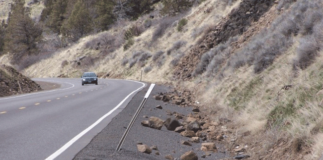
Figure 16: Rockfall in US 97 RSA Study Area.
To address these and other concerns, a two-phase road improvement project was adopted by ODOT. The Phase One work began in early 2005 and was in progress at the time of the RSA; it included replacement/repair of four bridges, as well as rockfall work and widening on the east side of the highway. The Phase Two work, with a projected completion date of November 2009, would comprise improvements on the west side of US 97–between the highway and the adjacent railroad tracks. Constraints included topography and steep slopes, rockfall issues, the adjacent Union Pacific Railroad right-of-way and culturally sensitive sites of the area’s Native American tribes, and the need for the road to not only remain open to traffic during construction but also maintain certain minimum lane widths to accommodate heavy truck traffic.
The RSA team reviewed safety conditions on US 97 utilizing recent crash data, local and RSA team inputs, and IHSDM. IHSDM was used to help select sites for detailed review and to help identify priority areas where improvements should be considered. The project team utilized three IHSDM modules: the Policy Review Module (PRM), the Design Consistency Module (DCM), and the Crash Prediction Module (CPM).
The IHSDM analysis produced output tables and graphs that illustrate locations where stopping sight distance was not met, where the differential in speed from a tangent section to subsequent horizontal curve are a concern, and where crash potential is elevated. The results by module are summarized as follows:
PRM: The available stopping sight distance at two locations did not meet the minimum criteria set forth by the 2004 AASHTO "Green Book." In Figure 17 are the available sight in gold for the northbound direction and in blue for southbound). Note the circle on the graph indicates a location where a combination of critical elements identified by IHSDM are present. This location was one of the most critical based on PRM and DCM output.

Figure 17: A Section of US 97 IHSDM PRM Stopping Sight Distance Graph.

Figure 18: Sight distance is limited on horizontal curves with barriers.
DCM: The output from this module showed that the expected reduction in estimated 85th percentile speeds from an approach tangent to its succeeding horizontal curve were all flagged as "green," indicating the speed differential is less than 6 mph (in Figure 19, see 85th percentile speed plotted for the northbound direction with green flags indicating speed differential). Two horizontal curve locations that approached this threshold were noted, but overall design consistency was fairly uniform. Note the circle on the graph indicates a location where a combination of critical elements identified by IHSDM are present. This location was one of the most critical locations based on PRM and DCM output.
, KValue (ft/%), Radius (ft), Degree of Curve (dcg), and speed (mph).")
Figure 19: Summary of US 97 IHSDM DCM Results.
CPM – Five years of historical crash data–including 74 reported collisions from January 1, 2000 to December 31, 2004– were considered by the CPM analysis for the section of the alignment from milepost 262 to milepost 267.2. The expected crash rate (crashes/mi/yr) for each homogeneous roadway segment and horizontal design element was graphed as part of the default IHSDM output (see Figure 20). The results indicated that expected crash rates are higher at horizontal curves with short radii.

Figure 20: Summary of US 97 IHSDM CPM Results on Segment Evaluated as Part of RSA.
A summary of the key RSA findings and suggestions is shown in Table 7.
Table 7: US 97, Klamath County, Oregon: Key safety issues and suggested mitigating actions.
| Selected Safety Issue | Suggested Action |
|---|---|
| Roadside safety issues There were steep slopes and ditches within the clear zone, unprotected utility poles, and shoulder edge-drops. |
Additional roadside barriers. Relocation or shielding of utility poles. Use Safety Edge to limit edge-drops. |
| Sight distance Sight distance was constrained by roadside topography, rockfall fences, and bridge superstructures at horizontal curves and at intersections. |
Confirm stopping sight distance. Review of specified sight distance obstructions at intersections and improve as needed. |
| Limited night-time guidance There was limited night-time guidance provided on this curved alignment with steep side slopes. An enhanced level of delineation would be beneficial along this hazardous segment of roadway. |
Enhanced post-mounted delineators. Improved centerline and edgeline delineation. |
| Signage Signing issues included possible re-use of faded signs, missing intersection warning signs, and use of small lettering on street name signs. |
Intersection warning signs. Advance street name signs and larger street name signs. Confirm retroreflectivity of reused signs and replace as necessary. |
| Rockfall protection Rockfall protection formed an important part of the design requirements. The very challenging improvement site may be a candidate for the use of enhanced rockfall protection measures. |
Enhanced rockfall protection measures if standard measures are ineffective, infeasible, or create other undesirable conditions. |
| High speeds High speeds contributed to increased collision risk and severity. |
Use IHSDM speed profiling in speed enforcement efforts. Variable speed limits. |
| Winter weather A high proportion of crashes occurred under winter road conditions. |
Ice detection and warning system. |
IHSDM provided key inputs to the RSA team based on several modules that helped it to identify potential safety issues along the corridor. The use of IHSDM allowed a comparison between the existing available stopping sight distance and the stopping sight distance associated with the proposed design. It also predicted crashes along the future roadway based on its geometric characteristics and projected traffic volumes. IHSDM highlighted locations where drivers may need to decelerate to safely negotiate a horizontal curve, thereby assisting in the prioritization of locations for review by the RSA team.
The ability to quantify values associated with design issues (e.g., stopping sight distance) and to estimate future crash frequencies based on the road redesign enhanced the value of the RSA by demonstrating the magnitude of the safety issues identified by the RSA team. Without IHSDM estimates, the RSA team could identify–but could not necessarily quantify–expected changes in safety parameters such as operating speeds or expected crash frequencies. Quantifying these parameters and frequencies provided a higher level of confidence to all parties (the RSA team, Design Team, and Owner) concerning the magnitude and importance of the safety issues identified in the RSA.
Furthermore, opportunities for using IHSDM output beyond engineering were identified. Law enforcement indicated an interest in reviewing locations where speed may be a concern as identified by the DCM.
The data requirements by module are provided in this section.
The output from IHSDM can be used to identify potential issues for detailed field investigation by the RSA team and can help point to potential measures that may mitigate safety issues identified as part of the RSA process. IHSDM can help focus an RSA team's efforts to maximize the input from the multidisciplinary team. The analysis methods used for each of the modules are as follows.
The evaluation report for this module contains tables comparing user-specified elements against user-specified policies along with a graphical display of the stopping site distance and passing sight distance checks. The user may select from 17 policy checks, organized by category as follows:
For this effort the AASHTO 2011 policy provided in IHSDM was used to perform selected checks. The checks selected were:
The two-lane rural roads predictive method was utilized with site-specific crash data, which utilizes the Empirical Bayes (EB) procedure. This procedure combines expected crash frequencies (estimated using the safety performance functions and crash modification factors) with site-specific crash history data. The advantage of using the EB procedure is to improve the accuracy of estimates for an individual location by factoring in the actual crash history of the location being evaluated. In theory, when enough years of crash history data are available, it would be more accurate to appropriately combine estimates from the SPFs and CMFs with site-specific crash history data than to rely on either the model estimates or the site-specific data alone. The EB procedure determines the statistically appropriate weighting of estimates from the SPFs and CMFs and site-specific crash history data.
The predictive model for Rural Two-Lane, Two-Way Roadway Segments is described in Chapter 10 of the HSM. The CPM report provides tables with the highway and intersection data provided to conduct the evaluation, along with plotted expected crash frequencies and rates using the HSM predictive method.
Crash prediction models for roadway segments of Rural Two-Lane highways are composed of two analytical components: safety performance functions (SPFs), or baseline models, and crash modification factors (CMFs). There are also calibration factors that adjust the predictions to a particular jurisdiction or geographical area. The general form of the crash prediction models for roadway segments is:
Nrs = Nspf-rs x Cr x (CMF1r...CMFnr)where:
Nrs= predicted number of crashes for roadway segment per year;
Nspf-rs = predicted number of roadway segment crashes per year for nominal or baseline conditions;
Cr = Calibration factor for roadway segments developed for use for a particular jurisdiction or geographical area; (See the Highway Safety Manual, Appendix to Part C for details on calibration of the crash prediction models.)
CMFnr = crash modification factors for roadway segments.
The IHSDM approach to applying the predictive crash model relies on dividing the subject roadway into homogeneous segments, referred to as "sites." These segments are defined based on the locations of intersections, horizontal curves, vertical curves, and additional lanes or changes in average daily traffic or various roadway geometry attributes. The subject roadway is thus divided into a set of contiguous segments, or sites. The predictive crash model is used to calculate a crash estimate for each segment.
Crash estimates for each segment are dependent on the Crash Modification Factors (CMF) applied to the base model. A crash modification factor (CMF) is a multiplicative factor used to compute the expected number of crashes after implementing a given countermeasure at a specific site. CMFs are used to adjust the SPF estimate of predicted average crash frequency for the effect of individual geometric design and traffic control features, as stated in the crash prediction formula. CMFs in the range greater than 1.00 will increase the average crash frequency estimate, while CMF values below 1.00 will reduce the average crash frequency estimate. The IHSDM Predictive Crash methodology utilizes the following CMFs:
As part of this project, the IHSDM predictive crash model was used to evaluate crash potential for each of the RSA corridors. For the roadway segments evaluated on these corridors the differences in the predicted segment crash rates were primarily influenced by two specific CMFs: Horizontal Curves (CMF3r) and Grade (CMF5r). This finding suggests that the roadways’ curvature and grade contribute to a disproportionate number of crashes on these corridors. The following sections summarize the CMF calculations for horizontal curves and grade.
Horizontal Curves (CMF3r)
The base condition for horizontal alignment is a tangent roadway segment. The CMF for horizontal curvature is in the form of an equation and yields a factor. The CMF for length, radius, and presence or absence of spiral transitions on horizontal curves is determined using the following equation:
CMF3r = (1.55Lc + 80.2/R – 0.12S)/1.55Lc (3.7)where:
CMF3r = Crash Modification Factor for the effect of horizontal alignment on total crashes; Lc = Length of horizontal curve (miles) which includes spiral transitions, if present;
R = Radius of curvature (feet);
S = 1 if spiral transition curve is present; 0 if spiral transition curve is not present; 0.5 if a spiral transition curve
is present at one but not both ends of the horizontal curve.
Some roadway segments being analyzed may include only a portion of a horizontal curve. In this case, Lc represents the length of the entire horizontal curve, including portions of the horizontal curve that may lie outside the roadway segment of interest.
CMF values are computed separately for each horizontal curve in a horizontal curve set (compound curves). For each individual curve, the value of Lc used in the equation is the total length of the compound curve set and the value of R is the radius of the individual curve. If the value of CMF3r is less than 1.00, the value of CMF3r is set equal to 1.00.
Grade (CMF5r)
The base condition for the CMF for grade is a level roadway (0% grade). The following table (HSM Table 10-11) presents the CMF for grades. This CMF is applied to each individual grade segment on the roadway being evaluated without respect to the sign of the grade. The grade factors are applied to the entire grade from one point of vertical intersection (PVI) to the next (i.e., there is no special account taken of vertical curves).
Table 8: CMF for Grade for Roadway Segments (HSM, Table 10-11)
| Grade (%) | CMF5r |
|---|---|
| Level Grade (grade <= 3%) | 1.00 |
| Moderate Terrain (grade = 3% to 6%) | 1.10 |
| Steep Terrain (grade > 6%) | 1.16 |
Calibration factor was not applied to the RSA corridors selected for this study due to the availability of data to calibrate the models.
Calculates the expected reduction in estimated 85th percentile speeds from an approach tangent to its succeeding horizontal curve.
These measures are based on a speed-profile generated for a selected alignment. The steps in developing the speed profile are as follows:
Step 1 – Determine Preferred Speed
IHSDM determines the preferred speed on each horizontal highway element (i.e. horizontal tangents and curves) using different models.
Step 1a – Check Posted Speed
The Posted Speed is checked for the highway section. Different sets of models are used for higher speed highways vs. lower speed highways.
Step 1b – Determine Preferred Speed for Each Tangent
For higher speed highways, a desired speed is selected on tangents. For lower speed highways, the DCM predicts the preferred speed for each horizontal tangent using empirical speed prediction equations, based on data collected from tangent sites around the U.S. For tangents less than 150 ft in length, tangent Speed is a function of Posted Speed and Preceding Curve Radius. For tangents 150 ft or greater in length, tangent speed is a function of Posted Speed, Roadside Hazard Rating, and tangent Length.
Step 1c – Predict Preferred Speed for Each Curve
DCM predicts the preferred speed for each horizontal curve using empirical speed prediction equations, based on data collected from curve sites around the U.S. Speed is assumed to remain constant throughout a horizontal curve for both higher speed and lower speed highways.
For higher speed highways, curve speed is a function of curve radius and is affected by the vertical alignment. For lower speed highways, curve speed is a function of curve radius only.
Step 2 – Adjust Speeds for Acceleration and Deceleration
Speeds are adjusted using acceleration and deceleration characteristics of the evaluation vehicle selected for the analysis.
Step 3 – Preferred Grade-Limited Speeds Using TWOPAS Equations
Grade-limited speeds are predicted using TWOPAS equations. A second speed profile is generated, based on the vertical alignment and the evaluation vehicle selected for the analysis.
Step 4 – Select Lowest Speeds for Each Location
The lowest speed is selected for each location. The speed profiles from Steps 2 and 3 are compared and the lowest speed selected at each point along the alignment to create a final speed profile.
The DCM report contains a graph of the evaluation results on the speed profile along with a variety of geometric characteristics for the alignment. The report contains both graphical and tabular summaries of the DCM results.


