U.S. Department of Transportation
Federal Highway Administration
1200 New Jersey Avenue, SE
Washington, DC 20590
202-366-4000
|
|
|
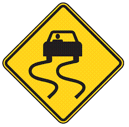
FIGURE 61 SLIPPERY WHEN WET sign. |
Figure 61 shows a sign with a black symbol of a car at the top of the sign. Two vertical wavy lines extend down from the car tires. The background of the sign is yellow.
|
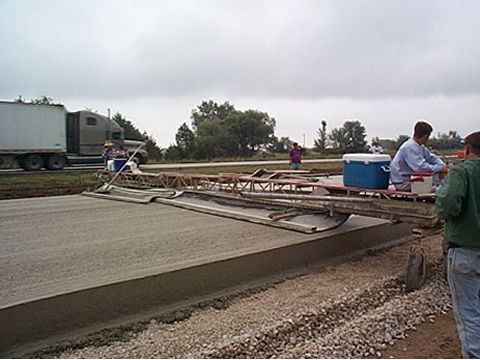
Target areas: High-speed roadways with insufficient cross slope. Strategy: SLIPPERY WHEN WET signing. The primary concern for locations with insufficient cross slope is inadequate drainage and ponding of water on the travel lanes. SLIPPERY WHEN WET signs may be used to warn drivers of pavements with insufficient cross slope that may become more slick than sections with normal cross slope (Figure 61). The MUTCD provides guidance on the size of warning signs for various highway types but notes that larger signs may be used when appropriate. Larger warning signs should be considered for design exception locations. Target areas: Any highway with cross slopes that are either too flat or too steep. Strategy: Grooved, textured, or open-graded pavements to improve surface friction. Another strategy aimed at helping drivers maintain control on slick pavements is pavement grooving and other textures that improve surface friction (Figures 62 and 63). This strategy is appropriate for pavements with cross slopes that are either too flat or too steep. For PCC pavement, textures can be placed at the time of construction or milled into existing pavement. Longitudinal grooving will minimize noise&mdash both externally and for drivers. For HMA pavement, open-graded surface courses can be used to improve surface friction. |
|
|
|
FIGURE 62 Longitudinal texture applied to fresh pavement to improve surface friction. |
Figure 62 is a photo showing equipment spanning the surface of fresh pavement. A mat is being dragged over the pavement to add longitudinal texture.
|
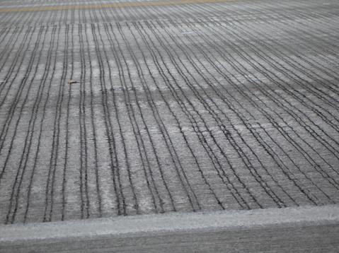
Target areas: Any highway with insufficient cross slope. Strategy: Improve drainage through transverse grooving on PC pavement and open-graded surface courses on HMA pavement. Improving drainage should be considered for roadways with insufficient cross slope. Transverse grooving on PCC pavement can improve surface drainage (Figure 63). On HMA pavement, open-graded friction courses with a higher percentage of voids allows water to drain more quickly through the surface course to an impervious intermediate course, and out into an edge drain or the ditch. This strategy should be considered on resurfacing projects in situations where the cross slope cannot be increased to the acceptable range. In some locations, more expensive continuous drainage systems may be appropriate (Figure 56). |
|
|
|
FIGURE 63 Transverse grooving to improve surface drainage and friction. |
Figure 63 is a close-up photo showing pavement with transverse grooving.
|
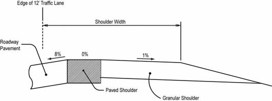
Target areas: Highly superelevated highways where the cross-slope break exceeds 8 percent. Strategy: Adjustment of the high-side shoulder cross slope. On the high side of superelevated curves, the cross-slope break should not exceed 8 percent. One mitigation strategy to consider is to move the breakpoint outward in the transverse direction (Figure 64), reducing the probability of a driver crossing over the breakpoint. Another strategy is to slope the shoulder in the same direction as the traveled lanes through the area with high superelevation. In northern regions, however, a downside to this strategy is that any ice or snow on the shoulder will drain onto the roadway as it melts during the day, creating the potential for ice to form on the traveled lanes as temperatures fall. Figure 64 illustrates how the cross slope of the shoulder can be transitioned to mitigate a steep cross-slope break. In this example, a portion of the shoulder is paved flat (no cross slope), adjacent to the steep cross slope of the travel lanes. The remainder of the shoulder is sloped in the opposite direction. This is an effective method for non-paved shoulders to prevent gravel or soil from washing onto the travel lanes and for controlling drainage across the travel lanes. There are additional ways to modify the cross-slope break, including rounding over the breakpoint on HMA pavements. |
|
|
|
FIGURE 64 An example of transitioning the cross slope of the shoulder to mitigate a cross-slope break greater than 8%. Rounding at the breakpoint is an option with HMA pavement. |