U.S. Department of Transportation
Federal Highway Administration
1200 New Jersey Avenue, SE
Washington, DC 20590
202-366-4000
Lane and shoulder width strategies have been combined in this discussion because normally they are evaluated in combination when there is limited cross-sectional width. The two criteria are also interrelated in terms of their effects on safety and operations.
|
Target areas: Highways with limited cross-sectional width. Strategy: Optimized lane and shoulder widths. In locations where cross-sectional width is constrained, evaluating how that width can be distributed most effectively between the lane and shoulder should be evaluated. This strategy is basically an exercise in trade&ndash offs&ndash taking some of the lane width to use for additional shoulder width or vice versa, depending on the location and the objectives. The optimal distribution will depend on site-specific characteristics. For example, on a rural two-lane roadway with no shoulders and a history of run-off-road crashes, an effective strategy may be to distribute some of the available width to accommodate a narrow paved shoulder and rumble strips, at the expense of narrower lanes. The objective would be to reduce the probability of run-off-road crashes. For another highway, with heavy truck volumes and a curvilinear alignment, maintaining full 12-foot lanes at the expense of some of the shoulder width may be a more-optimal design. The objective would be minimizing truck off-tracking into adjacent lanes or the shoulder. The key is to look at the site-specific characteristics such as highway type, traffic and truck volumes, geometry, crash history, and crash type. With this information, various combinations of lane and shoulder widths can be evaluated with the goal of optimizing safety and traffic operations at the design exception location. Case Study 1 (presented in Chapter 5) illustrates how one State evaluated multiple combinations of lane and shoulder width on a segment of urban freeway where the cross section was constrained. |
|
Target areas: High-speed roadways with narrow lanes. Strategy: Advance signing of narrow lanes. Signs can be used to warn drivers in advance of a change in lane width. Messages such as a ROAD NARROWS sign (Figure 26) may be used alone or in combination with an advisory speed plaque. The Manual of Uniform Traffic Control Devices (MUTCD) provides guidance on the size of warning signs for various highway types but notes that larger signs may be used when appropriate. Larger warning signs should be considered for design exception locations. Use of advance warning signs as a stand-alone measure is unlikely to sufficiently mitigate a design exception for lane width, but at some locations it can be an effective component of a more comprehensive approach. |
|
|
Target areas: High-speed roadways with narrow lanes or shoulders. Strategy: Enhance pavement markings. Another category of mitigation strategies for both lane and shoulder widths is aimed at enhancing a driver&rsquo s ability to stay within the lane. One method is to provide clear delineation and better visibility of the lanes. Wide pavement markings (Figure 27), recessed pavement markings with high retroreflectivity (Figure 25), and raised pavement markings (Figure 29) can help drivers stay within their lane&ndash particularly at night, when the pavement is wet or when visibility is poor. Both raised and recessed pavement markings will have higher costs than standard painting. Recessed pavement markings may provide extra advantages in areas of the country where snow and ice removal can cause additional wear on painted or raised markings. Target areas: High-speed roadways with narrow lanes or shoulders. Strategy: Delineators. |
|
FIGURE 26 Signs can be used to warn drivers in advance of a change in lane width. |
Figure26 shows a diamond-shaped sign with a border and the words ROAD NARROWS in black on a yellow background.
|
Target areas: Urban freeways and other high-speed urban roadways, or segments of high-speed rural roadways with a high crash history or high crash history or a higher probability of run-off-the-road crashes. Strategy: Lighting. Roadside delineators (Figure 30) can help drivers see changes in roadway geometry. Lighting (Figure 31) will have higher up-front costs and ongoing utility costs, but is another strategy that can enhance a driver&rsquo s ability to see and stay within the travel lane. Depending on the type of highway, traffic volumes, crash history, and other site-specific characteristics, lighting may be appropriate for the entire length of the design exception location, or it may be appropriate only for selected segments. For example, for a high-speed rural roadway with narrow lane or shoulder widths, lighting could be installed along horizontal curves or along segments with a history of lane-departure crashes. |
|
|
|
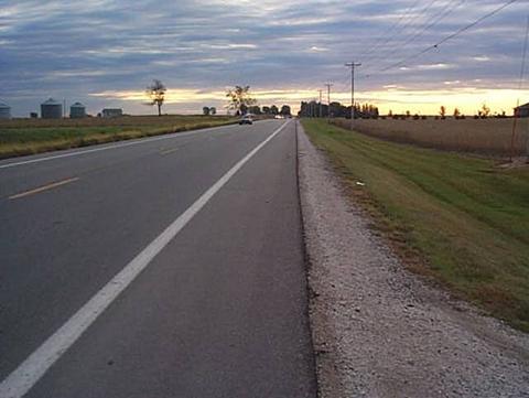
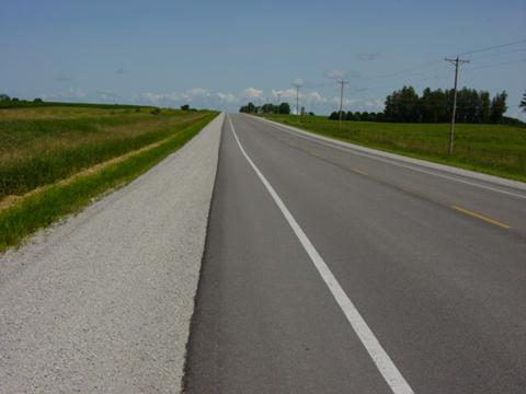
FIGURE 27 Wide pavement markings. |
Figure 27 is a photo of a road showing a wide (6-inch) pavement marking that indicates the outside limit of a lane.
|
|
|
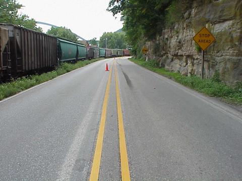
FIGURE 28 Recessed pavement markings. |
Figure 28 is a photo showing a recessed double yellow line running down the center of a road.
|
|
|
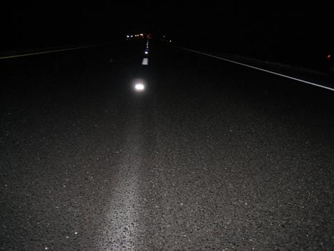
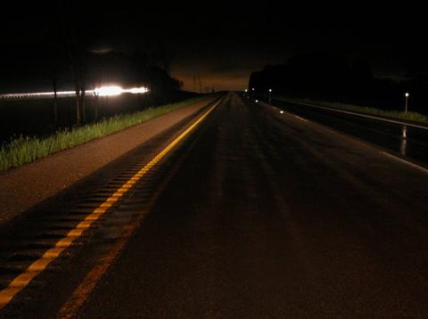
FIGURE 29 Raised pavement markings. |
Figure 29 is a nighttime photo showing raised pavement markers in combination with paintlines to improve visibility of the lane.
|
|
|
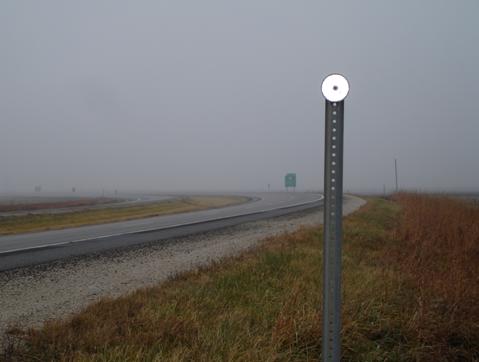
FIGURE 30 Post-mounted delineators. |
Figure 30 is a photo showing a post&ndash mounted delineator&ndash a circular reflective disk mounted on a metal post along the side of the road.
|
|
|
FIGURE 31 Lighting. |
Figure 31 is a photo showing high-mast light poles along an entrance ramp to a freeway.
|
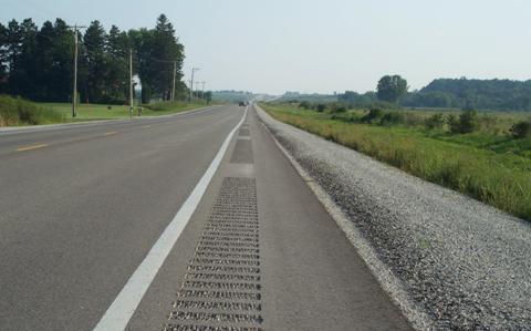
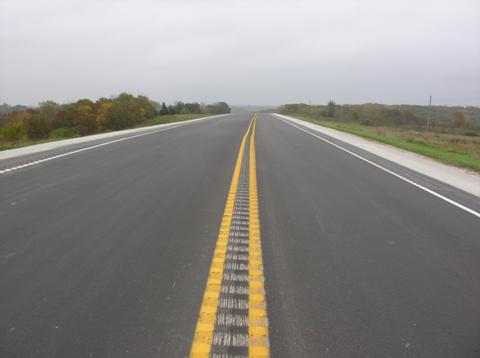
Target areas: High-speed rural highways. Strategy: Shoulder rumble strips. In addition to visible delineation, shoulder and centerline rumble strips improve a driver&rsquo s ability to stay within the lane by providing both an audible warning and a slight vibration within the vehicle that a driver can feel. On rural two-lane roadways with narrow lane widths, drivers may have a tendency to shy to the outside when meeting other vehicles. Shoulder rumble strips (Figure 32) warn drivers that they are outside the lane. Another concern on two-lane undivided roadways are cross&ndash centerline head-on or sideswipe crashes. Similar to shoulder rumble strips, centerline rumble strips (Figure 33) can be used to warn drivers that they are driving near the centerline and are close to encroaching on the opposing lane. Centerline rumble strips are normally used on high-speed rural two-lane highways. Shoulder rumble strips are an effective strategy on any high-speed rural highway. Agencies are encouraged to work in cooperation with local and state bicycle groups on shoulder rumble strip issues. By involving bicyclists early in the process, designs can be developed that achieve the safety benefits of rumble strips while at the same time accommodating the needs of bicyclists. The gap pattern illustrated in Figure 32 is one method that can be used to better accommodate bicyclists. Target areas: Two-lane, undivided, rural highways. Strategy: Centerline rumble strips. |
|
|
|
FIGURE 32 Shoulder rumble strips. |
Figure 32 is a photo showing the shoulder of a road with gapped rumble strips that have been milled into the shoulder pavement.
|
|
|
FIGURE 33 Centerline rumble strips. |
Figure 33 is a photo showing continuous rumble strips that have been milled down the centerline of the highway. Yellow centerline pavement markings have been painted over the rumble strips.
|
Target areas: High-speed rural highways and areas where snow removal operations are causing deterioration of pavement markings. Strategy: Painted edgeline rumble strips. An emerging strategy that has been tried in several States is combining edgeline pavement markings with shoulder rumble strips (Exhibit 4.9). The rumble strips are placed at the edge of the travel lane. This allows rumble strips to be placed on roadways with very limited cross-sectional width and narrow paved shoulders. The edgeline marking is then painted directly over the rumble strips. Several advantages of this strategy have been observed. First, the pavement marking on the near-vertical face of the rumble strip reflects more light back towards the driver at night, creating a more-visible edgeline. Second, in northern states, the paint and beads that are in the depressed portion of the rumble strip are less prone to wear from snow plowing. This can extend the life and performance of the painted edgeline. |
|
|
|
FIGURE 34 Painted edgeline rumble strips. |
Figure 34 is a nighttime photo showing shoulder rumble strips with the edgeline painted over the rumble strips. The painted edgeline on the rumble strips is highly visible compared to an adjacent edgeline that was placed on flush pavement.
|
Target areas: All high-speed highways. Strategy: Paved or partially paved shoulders. When a driver leaves the lane or the paved portion of the roadway at high speeds, there is a significant safety risk. As discussed in Chapter 3, pavement edge dropoffs can increase this risk. Paved or partially paved shoulders (Figure 35) move the pavement edge and potential dropoffs farther from the travel lane. Another strategy is to construct the pavement edge to allow safer recovery for drivers who leave the paved section of the roadway. The safety edge (Figure 36) accomplishes this by providing a beveled edge of pavement instead of a near-vertical edge. This strategy can be used with both hot mix asphalt (HMA) and portland cement concrete (PCC) pavements. Working with contractors is recommended because some modifications to paving equipment will be necessary. The safety edge is particularly worth considering for areas with very limited cross-sectional width, where there is not enough width for paved or partially paved shoulders. Many roadways on the local system fit this description. Target areas: High-speed highways, especially those with no paved shoulder or narrow paved shoulders. Strategy: Safety edge. |
|
|
|
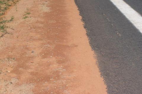
FIGURE 35 Partially paved shoulders. |
Figure 35 is a photo showing a shoulder that consists of both a paved area and gravel area.
|
Target areas: Any high-speed or rural highway. Strategy: Clear recovery area, traversable slopes, breakaway safety hardware, and barriers where appropriate. Because the probability of run-off-road crashes is higher at locations with design exceptions for lane or shoulder width, special attention should be paid to providing clear recovery areas and implementing measures to reduce the severity of these crashes Fixed objects should be removed (Figure 37) or relocated to a place where they are less likely to be hit&mdash at or beyond the clear zone, if possible. Signs, light poles, and other necessary roadside hardware should be installed with crashworthy breakaway supports (FIgure 38). Foreslopes, transverse slopes, and drainage structures should be made traversable. In some cases, fixed objects or steep slopes should be shielded with barriers (Figure 39). Although the use of barriers may increase crash frequency, crash severity is expected to decrease. |
|
|
|
|
|
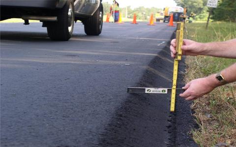
FIGURE 36 Safety edge (top photo) and after the shoulder has been graded over the edge (bottom photo) |
Figure 36 consists of two photos. The top photo shows a pavement edge that was constructed with a beveled edge (approximately a 45-degree angle). The bottom photo shows the pavement edge after granular material has been graded on top of the beveled edge.
|
|
|
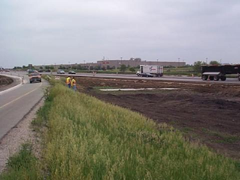
FIGURE 37 Fixed object removal. Separate box culverts were extended, connected, and covered at this interchange. |
Figure 37 is a photo showing an area between a freeway exit ramp and the freeway mainline. The photo shows the top of a box culvert that has been extended and connected between the ramp and the mainline that will be graded over, thereby eliminating a hazard for a driver who has left the roadway.
|
|
|
|
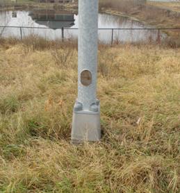
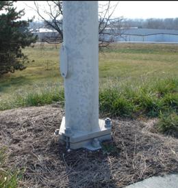
FIGURE 38 Breakaway light poles. |
|
Figure 38 consists of two photos showing two types of breakaway light poles&mdash a transformer base on the left and a slip base on the right.
|
|
|
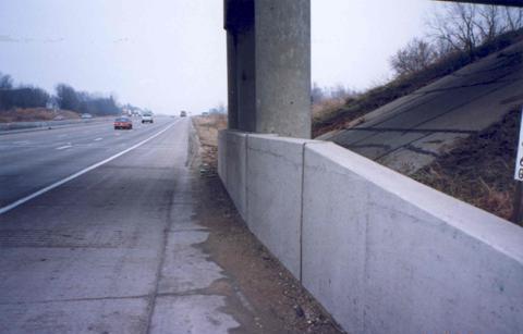
FIGURE 39 Shielding fixed objects with barrier. |
Figure 39 is a photo showing the piers of a highway overpass placed behind a concrete barrier next to the shoulder of the road.
|
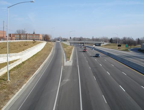
Target areas: High-speed roadways with narrow shoulders. Strategy: Pull-off areas. Where shoulder width is limited, another mitigation strategy is to provide regularly spaced pull-off areas (Figure 40). Pull-off areas provide several advantages. First, they provide room to store disabled vehicles, which is particularly important for maintaining operations on high-volume highways. A disabled vehicle can be parked or quickly removed from a travel lane to a pull-off area, allowing traffic to flow in all available traffic lanes as quickly as possible. Second, pull-off areas provide an area for law enforcement to detain vehicles in areas with narrow shoulders. This increases safety for law enforcement personnel, the stopped driver, and passing drivers. Operations are likely to be improved as well because drivers are more likely to maintain normal speeds and stay within their lane if law enforcement activities are being conducted a sufficient distance from the travel lanes in a pull-off area. If possible, pull-off areas should be located where lane departure crashes are less likely, such as tangent sections or on the inside of horizontal curves. Case Study 4 (presented in Chapter 8) illustrates how one State is using pull-off areas on a historic urban freeway with extremely narrow shoulders. |
|
|
|
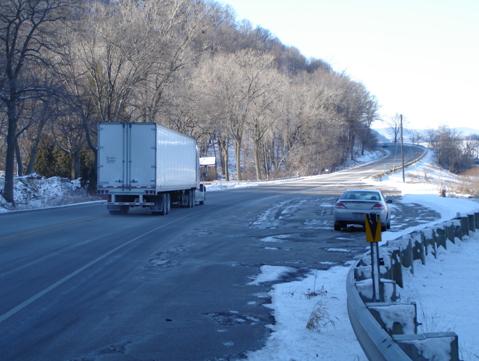
FIGURE 40 Pull-off area on the inside of a horizontal curve. |