U.S. Department of Transportation
Federal Highway Administration
1200 New Jersey Avenue, SE
Washington, DC 20590
202-366-4000
The strategies for mitigating sight distance problems are aimed at mitigating sight distance restrictions, improving drivers&rsquo ability to avoid crashes, and improving driver awareness on the approach to intersections.
|
Target areas: Crest vertical curves. Strategy: Signing. The MUTCD provides guidance on the size of warning signs for various highway types but notes that larger signs may be used when appropriate. Larger warning signs should be considered for design exception locations. Use of advance warning signs as a stand-alone measure may not be sufficient to mitigate a design exception for stopping sight distance, but at some locations it can be an effective component of a more comprehensive approach. Target areas: Sag vertical curves. Strategy: Lighting. Because headlight sight distance is the control at sag vertical curves, the most common mitigation measure at these locations is to install lighting. |
|
|
|
FIGURE 57 Sign for crest vertical curve with inadequate stopping sight distance. |
Figure 57 shows a diamond-shaped sign with the words HILL BLOCKS VIEW on three lines. The sign is yellow with a black border and legend.
|
Target areas: Horizontal curves. Strategy: Lower-height barrier. One common horizontal sight obstruction is concrete barrier. Lower-height barrier should be considered in these situations. There are vertical-shaped concrete barriers in the height range of 29 to 32 inches that are compliant with NCHRP Report 350 criteria at test-level 4 (crash testing with a single-unit truck at 60 mi/h). Case Study 4 (presented in Chapter 8) illustrates how one State is using a lower-height median barrier to maximize horizontal sight distance. Target areas: Horizontal curves. Strategy: Adjusting placement of lane within the roadway cross section. In some cases, slight adjustments to lane width or the placement of the lane within the roadway cross section can increase horizontal stopping sight distance. This strategy must be evaluated carefully to ensure that it does not create other safety or operational problems, particularly if the lanes are narrowed. |
|
Target areas: Any location with limited stopping sight distance. Strategy: Select cross-sectional elements to manage speed. In some locations, mitigation measures to consider for either vertical or horizontal sight distance design exception locations are cross-sectional elements and dimensions that manage operating speeds so they are at or below the speeds corresponding to the available sight distance. For example, an urban cross section with curb and gutter gives the driver a visual cue that they are in a reduced-speed environment. A more-closed cross section may also affect driver comfort and cause drivers to slow down. This strategy should not create additional design exceptions. |
|
Target areas: Any location with limited stopping sight distance. Strategy: Provide wider shoulders and wider clear zones. Where there is insufficient sight distance to vehicles or other objects on the roadway ahead, a fundamental strategy is to design shoulders and a roadside that will improve a driver&rsquo s ability to avoid a crash. Wider shoulders will give drivers a better chance to safely avoid a crash and remain on the roadway. Providing additional clear recovery area on the roadside will reduce the probability of a severe run-off-the-road crash if the driver leaves the roadway. |
|
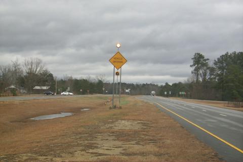
Target areas: Any location with limited sight distance to an intersection. Strategy: Static or dynamic warning of intersection or entering traffic. At some locations, the visibility of approaching intersections and associated traffic control devices may be restricted because of inadequate horizontal or vertical sight distances. Mitigation measures can be implemented to make the driver more aware of the intersection. Advance signing can be installed to warn drivers of the intersection before it is clearly visible. In some situations, flashers installed in conjunction with the sign may further increase driver awareness. At intersections with a high crash history, high traffic volumes, severe sight restrictions, or other concerns, ITS applications may be appropriate strategies. For example, detectors can be placed in the pavement on a minor road approach to a major highway. A flasher on the major highway can be installed to warn drivers that vehicles are at the minor road approach, entering the intersection (Figure 58). |
|
|
|
FIGURE 58 Intersection warning sign with flashers activated by vehicles entering on the side road. |
Figure 58 is a photo of a post-mounted diamond-shaped sign within the median of an expressway with the words VEHICLE ENTERING on two lines. The sign is yellow with a black border and legend, and has flashers mounted above and below it. Beyond the sign in the photo, an intersecting road with vehicles on it is visible.
|
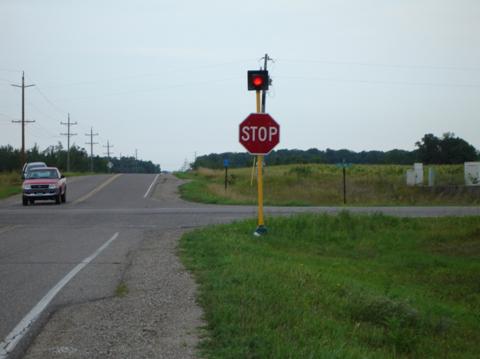
Target areas: Any location with limited sight distance to intersection signs. Strategy: Repositioning, adding, or enhancing intersection signs. Measures can also be taken if the sight distance to traffic control devices at an intersection is limited. Examples include: installing larger STOP or YIELD signs, installing STOP signs on both sides of the roadway, adding a STOP sign on the left side near the centerline within an island, and installing a flasher on top of the STOP sign to improve visibility because of limited vertical sight distance (Figure 59). |
|
|
|
|
|
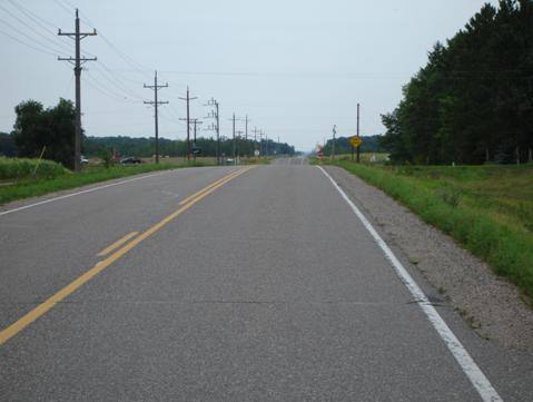
FIGURE 59 A STOP sign with a flashing beacon improves visibility of the sign at this intersection with limited vertical sight distance. |
Figure 59 consists of two photos. The first photo shows a stop sign in the distance with a red flashing beacon mounted above the sign, visible over the top of a crest in the road. The second photo shows the stop sign and beacon up close, near the intersection with another road that is now visible.
|
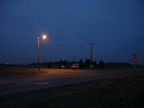
Target areas: Any location with limited sight distance to an intersection, particularly intersections with a history of night crashes. Strategy: Intersection lighting. Another strategy for improving intersection recognition, particularly where there is a history of night crashes, is intersection lighting (Figure 60). |
|
|
|
FIGURE 60 Intersection lighting. |
Figure 60 is a photo showing a four-way intersection illuminated by a pole-mounted light in one quadrant of the intersection.