U.S. Department of Transportation
Federal Highway Administration
1200 New Jersey Avenue, SE
Washington, DC 20590
202-366-4000
After concluding that providing an inside shoulder that met full criteria was not feasible, the designers initially considered full 12-foot (3.6-m) lanes with 7-foot (2.1-m) inside shoulders. The first mitigation measure investigated was to slightly reduce lane width to provide a wider inside shoulder. The safety goal was to provide enough inside shoulder width to store disabled vehicles and allow drivers to maneuver onto the shoulder to avoid a crash or an object in front of them on the traveled lanes. An 8-foot (2.4-m) shoulder was determined to be the minimum width for safe storage of disabled vehicles next to the concrete median barrier. The wider shoulder also slightly increased horizontal stopping sight distance around the 44-inch median barrier.
As listed in Table 23, a number of combinations were considered, and there was much discussion about the tradeoffs associated with each of the alternatives. As part of the analysis, the Iowa DOT consulted a study by the Texas Transportation Institute related to lane and shoulder widths on urban freeways.
|
Combinations of lane and shoulder widths that were considered |
||
|
Lane Width |
Inside Shoulder Width |
Comments |
|
12 feet (3.6 m)—all thru lanes |
12 feet (3.6 m) |
Meet all design criteria. Widen to the outside. |
|
12 feet (3.6 m)—all thru lanes |
7 feet (2.1 m) |
Use available width to accommodate full lane widths. Design exception for shoulders only. |
|
11.5 feet (3.5 m)—all thru lanes |
9 feet (2.7 m) |
|
|
11.0 feet (3.4 m)—all thru lanes |
10 feet (3.0 m) |
|
|
11.5 feet (3.5 m)—inner 2 lanes in each direction |
8 feet (2.4 m) |
Selected design. |
|
11.0 feet (3.4 m)—inner two lanes in each direction |
9 feet (2.7 m) |
|
|
Alternatives were also discussed that used some of the outside shoulder width. |
||
Parts of the freeway project did not include full pavement replacement, including the design exception area. A thick HMA overlay was placed over the existing portland cement concrete lanes. With the possibility of reflective cracking, one issue that needed to be considered was how such cracks would line up with the proposed lane lines. Because narrowing the lanes would place the new lane lines at a different transverse position than the longitudinal joints of the underlying PC pavement, there was some concern that if cracking were to occur, drivers would position their vehicles relative to the crack instead of the pavement markings. This could be even more prevalent when sun glare or inclement weather obscures the pavement markings.
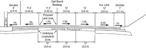
This issue influenced which lanes were narrowed and by how much, as the designers strived to line up the proposed lane lines with the underlying joints as closely as possible (Figure 77), while at the same time achieving a wider and more useable inside shoulder (Figure 78).
|
|
|
FIGURE 77 Narrower lane widths would place the lane lines in a different transverse position than the underlying longitudinal joints. |
Figure 77 is a drawing showing the new HMA pavement over the existing PCC pavement. Because of the narrowed lane and shoulder widths used through the design exception area, the underlying longitudinal joints in the existing pavement do not line up with the new lane lines.
In addition to the reflective cracking issue, there were several other reasons that 11.5-foot lanes on the two inside lanes were ultimately chosen. First, the designers concluded that more than a 6-inch deviation from the adopted criteria for lane width was not appropriate for a high-volume urban interstate or for the specific characteristics of this location. Second, 6-inch lane width reductions, on a total of four lanes, provided enough space for inside shoulders wide enough to accomplish the safety objectives. Third, the right-side lanes would experience more maneuvering and lane changing as vehicles entered and exited the freeway than would the inside lanes. Therefore, full lane widths were maintained on the two outside lanes in each direction.
Other elements that were considered in the analysis included the following:
Horizontal alignment. A relatively straight horizontal alignment, with no non-standard horizontal curvature through the design exception area, supported the concept of narrowed lanes. The potential for large vehicles to off-track along curves and encroach into adjacent lanes is an issue that should be considered when lane widths are being studied.
Volume of trucks and other large vehicles. Wider vehicles such as trucks, buses, and recreational vehicles need adequate lane width for driver comfort. Operationally, lane widths that are too narrow may cause drivers of large vehicles to drive slower than the prevailing operating speeds. This issue is also interrelated with horizontal alignment, because larger vehicles will off-track to a greater degree around curves. Although there is some large vehicle traffic on Interstate 235, much of it bypasses the city on Interstates 80 and 35 along the north and west sides of the metro area (Figure 71). This fact also supported the concept of slight lane width reductions. Large vehicles in the innermost lane will also be adjacent to the 8-foot inside shoulder, which increases the comfort level for drivers in that lane.
Speeds. The posted speed limit for Interstate 235 is 55 mi/hr, with operating speeds slightly higher during non-peak hours. The lower speeds of an urban freeway, as compared to most rural freeways and expressways, also supported the proposed design.
Substantive safety. Crash data from the 1990s were evaluated and showed that shoulder width was not a contributing factor to the crashes within the design exception area.
|
|
|
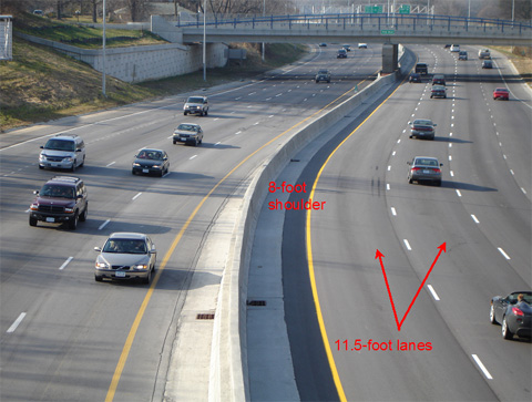
FIGURE 78 Inside lane and shoulder widths within the constrained areas were narrowed. |
Figure 78 is a photo of a reconstructed portion of Interstate 235, showing all lanes in both directions within the area of limited cross-sectional width. The wider 8-foot inside shoulder is marked in red lettering, as are the narrower 11.5-foot travel lanes.
To deal with the concern of the adjusted lane lines not matching up with potential reflective cracks, high-reflective pavement markings were used to better delineate edges of the lanes. Because these pavement markings are recessed, they also require less frequent re-application compared to flush, painted markings that are more prone to wear from snow and ice removal.
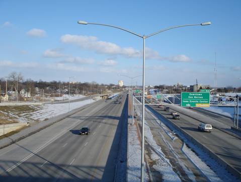
The 8-foot inside shoulders provide space for emergencies and incidents. It is insufficient, however, for most maintenance activities requiring vehicles in the median. A final mitigation measure involved the elimination of one important maintenance operation in the median. Overhead lighting was shifted to the outside of the freeway through the design exception area, instead of on top of the median barrier (Figure 79). This allows lighting maintenance to take place on the outside, where there is more space, instead of within the 8-foot inside shoulder, which would require closure of the inside lane. Another reason for doing this was to prevent vehicle intrusion with light poles when the barrier is struck by large vehicles. In the area with the greatest cross-sectional width and a split median barrier, lighting was placed down the median (Figure 80).
|
|
|
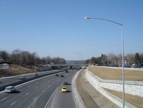
FIGURE 79 Lighting was placed on the outside of the freeway through the design exception area. |
Figure 79 is a photo showing the placement of light poles on the outside of the freeway through the design exception area.
|
|
|
FIGURE 80 Lighting was placed down the center of the median where more cross-sectional width was available. |