U.S. Department of Transportation
Federal Highway Administration
1200 New Jersey Avenue, SE
Washington, DC 20590
202-366-4000
November 2008
| 1. Report No. FHWA FHWA-SA-08-002 | 2. Government Accession No. | 3. Recipient's Catalog No. | |||
| 4. Title and Subtitle W-Beam Guardrail Repair: A Guide for Highway and Street Maintenance Personnel | 5. Report Date August 2008 | ||||
| 6. Performing Organization Code | |||||
| 7. Authors William J. Fitzgerald, P.E. | 8. Performing Organization Report No. | ||||
| 9. Performing Organization Name and Address | 10. Work Unit No. | ||||
| Vanasse Hangen Brustlin Inc 8300 Boone Boulevard, Suite 700 Vienna, VA 22182-2626 |
PerformTech, Inc. 810 King Street Alexandria, VA 22314 |
11. Contract or Grant No. DTFH61-05-D-00024 | |||
| 12. Sponsoring Agency Name and Address Office of Safety Federal Highway Administration U.S. Department of Transportation 1200 New Jersey Avenue, S.E. Washington, D.C. 20590 |
13. Type of Report and Period Covered Final Report | ||||
| 14. Sponsoring Agency Code | |||||
| 15. Supplementary Notes: The FHWA Office of Safety Contract Task Order Manager was Dr. Clayton Chen. The Technical Oversight Working Group included Ed Denehy-NYSDOT, Tom Nutini-Franklin Co, OH, Dennis Randolph-Calhoun Co, MI, Gary Rohrer-Washington Co, MD, and Glenn Schulte-UDOT. | |||||
| 16. Abstract Roadside barriers are a critical safety device as they shield motorist from what might be a more severe crash when leaving the roadway. Therefore, when damaged they need to be repaired so that they can perform this function. The purpose of this guide is to provide highway and maintenance personnel with up-to-date information on how to repair damaged W-Beam guardrail, the most frequently used barrier system. Three levels of damage are described and guidance is provided on the need and procedure for appropriate repairs. Appendices provide information on the resources (equipment, tools, crew, and time) that will be needed and forms for inspection and maintenance. This guide is an update of a document, W-Beam Guardrail Repair and Maintenance: A Guide for Local Highway and Street Maintenance Personnel, published in 1990 by FHWA. | |||||
| 17. Key Words W-Beam guardrail, repair, maintenance | 18. Distribution Statement No restrictions. This document is available to the public through the National Technical Information Service, Springfield, VA 22161. | ||||
| 19. Security Classif. (of this report) Unclassified | 20. Security Classif. (of this page): Unclassified | 21. No. of Pages: 53 | 22. Price | ||
This guide was prepared by Vanasse Hangen Brustlin, Inc. (VHB) under FHWA Contract DTFH61-05-D-00024. Ms. Leslie Wright, Federal Highway Administration Office of Safety, was the initial Task Order Manager; she was replaced by Dr. Clayton Chen. The principal investigator and author was William J. Fitzgerald, P.E. as a consultant from PerformTech, Inc., to VHB. Technical editing was provided by Dr. Hugh McGee, P.E. and Ms. Vicki Glenn and document preparation was performed by Ms. Michelle Scism, all from VHB.
A Technical Working Oversight Group was formed to guide the preparation of this document. The members included:
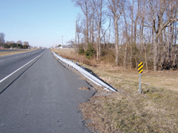
Ideally, highways should be designed so there is no need for roadside barriers; unfortunately, this is seldom practical. Bridge piers, steep side slopes, non-breakaway sign or luminaire (street light) posts, or other similar features along the road create potential dangers to drivers who leave the roadway. Because barriers themselves are potential hazards, use them only when necessary to shield a condition that could be significantly more hazardous. For example, crews may be able to modify a non-traversable, potentially dangerous drainage inlet to be safely traversable, making installation of a barrier unnecessary. Should the potential hazard be a steep embankment, a bridge pier, or a large sign support, installing a barrier may be the best option for preventing serious injury or fatality.
Deciding whether to install barrier can be a complex decision. Guidance on when and where to install a barrier can be found in the Roadside Design Guide (see reference list). However, once a barrier is installed, road crews must maintain it and repair it to ensure it functions as intended.
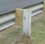
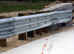
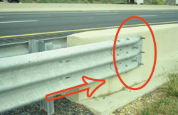
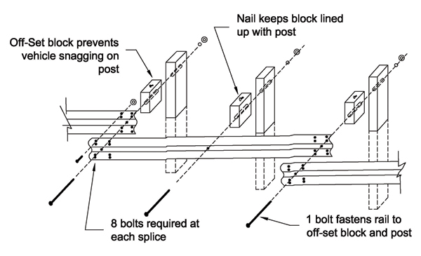
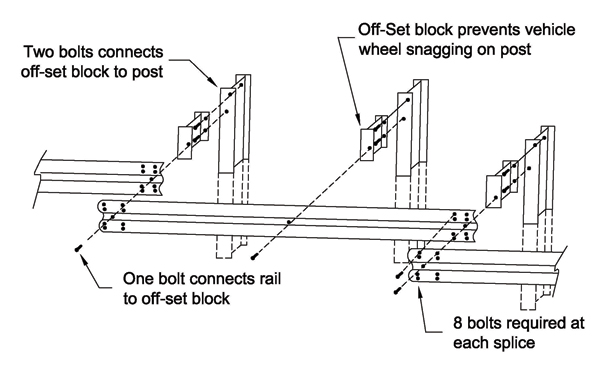
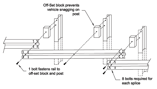
Strong post W-beam guardrail with wood block and metal post.
This guide focuses on how to repair (not design) the most widely used barrier–the strong post W-beam guardrail identified as SGR-04 in the Standardized Highway Barrier Hardware Guide. (The term guardrail, and in some states guiderail, is commonly used either for just W-beam barriers or for barriers in general; for future use in this guide, the term W-beam guardrail will refer to the strong post W-beam barrier system.) The standard strong post W-beam guardrail consists of a W-beam rail element and strong posts (wood or steel) spaced at 6 ft3 in with the rail blocked out from the posts. Although the focus is the strong post system, much of the guidance that is provided for the repair of the strong post design can apply to the weak post design as well.
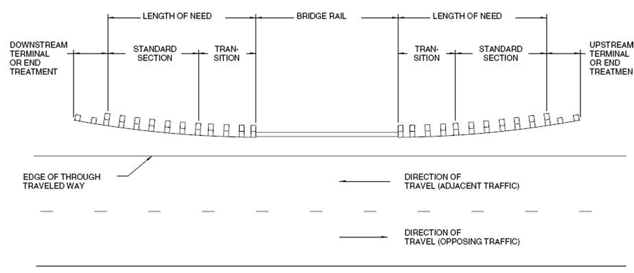
This guide is structured around the three sections of a guardrail that have variations in design to serve their purposes:
The next chapter identifies three levels of damage resulting from impacts into each section and suggests corrective action. Chapter III provides basic guidance on repair sequence and Chapter IV discusses record keeping. Appendix A addresses estimating parts and materials and identifying resources (work crews and equipment) needed for typical repair work and includes two examples of damage inspection reports and a tool for estimating the radius of curved guardrail elements. Appendix B provides one State's guardrail repair guidelines. Although this guide is for guardrail repair, Appendix C provides guidance for maintenance activities that improve the likelihood that barriers of all types will perform as intended. Finally, Appendix D provides a description of the clear zone, an important safety feature for all roads. References are found after Chapter IV.
Road agencies can learn of damaged guardrail from several sources, an accident report is the most obvious. However, as many guardrail impacts are drive-away situations, maintenance (or other highway) personnel can identify damage that may not be obvious to the casual observer, but that could keep the guardrail from performing as intended. Once the agency receives notice of damage, make an on-site review of the damage. The first priority of a review is to determine whether the barrier can be removed — by eliminating the hazard it was intended to shield. This is seldom an option, but do not lose the opportunity to improve the roadside safety. If the barrier is to remain, then the review objective is to determine the extent of the damage, what repairs to make, and when to make them.
Three categories of functionality can be used to describe the extent of damage:
Each agency must make a risk assessment about the timing of repair for each different category of functionality. The assessment would include, among other factors, agency resources (within its overall mission), hazard exposure (how likely is it the guardrail will be hit again), and hazard severity. It is important that each agency develop guidance for when to make repairs.
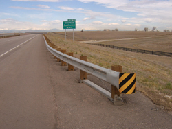
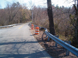 Drums, as shown, vertical panels, or cones, can be used to warn drivers of the damaged guardrail until it can be repaired.
 Upon arriving at the site, clear any debris from the traffic lanes and shoulders. Place debris that cannot be hauled away at least 3 ft behind still-effective guardrail. When the damage leaves the guardrail nonfunctional, and it cannot be repaired immediately, warn traffic of the hazard by putting out temporary warning devices, such as drums, vertical panels, cones, or other devices, in accordance with the Manual on Uniform Traffic Control Devices (MUTCD), Part 6, Temporary Traffic Control, or local policy.
If a blunt end remains, take steps to minimize its danger. Crews could drop the rail forming a turndown; while not desirable, it is better than leaving a spear. In extremely dangerous situations, use a truck-mounted attenuator (TMA) or other type of attenuator. If possible, smooth any rough grading caused by the impact. Make a damage inspection report detailed enough to estimate repair parts and resources needed. Appendix A provides a sample damage inspection report (Item 1); provides information on estimating parts and materials (Item 2), equipment and tools (Item 3), time needed (Item 4), and crew size (Item 5); and a sample repair log (Item 6).
For each of the three sections of the W-beam guardrail system, the following is provided: the function of the section, examples of extent of damage, proper repair techniques, and a checklist for repairs.
The function of the standard W-beam section is to prevent penetration by a vehicle, either through, over, or under the W-beam and to smoothly redirect the vehicle. You can use the chart below to determine the functionality category based upon the damage to the standard section of the W-beam guardrail.
| EXTENT OF DAMAGE | FUNCTIONALITY | ||
|---|---|---|---|
RAIL ELEMENT SEPARATED |
1 |
||
| RAIL ELEMENT TORN | 1 | ||
| TOP OF RAIL HEIGHT ≤ 24" | 1 | ||
RAIL ELEMENTS INTACT FULL SPLICES TOP OF RAIL HEIGHT > 24"* |
AMOUNT OUT OF ALIGNMENT | AMOUNT OF BROKEN/BENT OR SEPARATED POSTS | 3 |
<6" |
0 | ||
| 1-2 | 2 | ||
| ≥3 | 1 | ||
| 6" – 12" | 0-2 | 2 | |
| ≥3 | 1 | ||
| ≥18" | NOT APPLICABLE | 1 | |
FUNCTIONALITY CATEGORIES:
1 Guardrail no longer reasonably functional
2 Guardrail should function adequately under a majority of impacts
3 Should not impair the guardrail's ability to perform
In narrative format, this chart shows: Functionality category 1 applies to any damage where the rail element is separated or torn, or the rail height is equal to or less than 24 inches. Category 1 also applies even if none of these three conditions exist, but (1) there are three or more broken, bent, or separated posts and the amount out of alignment is 12 inches or less, or (2) if the amount out of alignment is equal to or greater than 18 inches regardless of any broken, bent or separated posts. Functionality category 2 applies if the guardrail is out of alignment no more than 12 inches and no more than two broken, bent, or separated posts. Functionality category 3 applies only if the guardrail has no damage other than being out of alignment by less than 6 inches.
1. Damage: Guardrail no longer reasonably functional.
Rail is bent/pushed more than 18 inches out of line, and/or became less than 24 inches high, or three or more posts are broken/bent over and separated from the rail.*
2. Damage: Guardrail should function adequately under a majority of impacts.
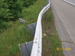
Rail is bent/pushed out of line less than 12 inches – rail element is intact (no tears and full splices).*
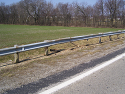
One or two posts are broken/bent over and separated from the rail – rail element is intact (no tears and full splices).*
3. Damage: Should not impair the guardrail's ability to perform.
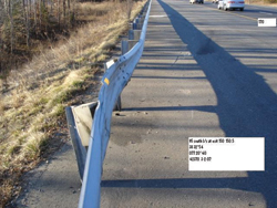
Rail is bent/pushed out of line less than 6 inches – rail element is intact (no tears and full splices; guardrail height is minimum 26-inches).*
*This is the best guidance currently available. An NCHRP study is under way to determine the level of damage that should not affect barrier functionality.
The primary mechanism enabling guardrail to redirect a vehicle is tension developed in the rail element. Therefore, all repairs must ensure that full-tension capability is reestablished. The strong posts contribute to smooth redirection by limiting the amount of deflection and providing consistent stiffness along the rail to prevent pocketing. Repair all posts to a condition enabling them to perform their function.
A second critical element of functional W-beam is proper height. Full-scale tests show that 25-in-high W-beam (measured to the top of the rail element) will not contain a design impact (a 4,400-lb pick-up truck at 62 mi/h and a 25° impact angle).
If the length of damaged W-beam is significant, then repair the barrier to meet the current standard for height. For short sections (one or two panels) of repair, it generally is not practical to adjust the current height. When the whole run of the W-beam guardrail is substantially (3 inches or more) below the current standard (and is not repaired at this time), report the situation to management to ensure it is included in future W-beam upgrade projects.
Ensure all repaired guardrail meets your agency's current standard (except related to height, as discussed above). For repair only, use posts of a material different than the existing material only when it is impractical to obtain like-material posts. The length of W-beam to be repaired should depend on the total length of barrier and the extent of damage. If damage is severe and either the length of the whole installation is short or the amount of damage is greater than a certain percent of the total length, then bring the total system to current agency standard (including height). Values for these two criteria are arbitrary and should be set by the agency. Appendix B provides an example of one State's criteria (Note: the height criteria included in this example do not conform to the guidance in this booklet). Typical values are 100 to 200 ftto define short length and 50 percent to define portion of total length needing repair.
There is an exception to the recommendation in the previous paragraph to meet current agency standards: When existing steel post/steel block out W-beam needs repair, and it is not against agency policy, crews can use (or install) steel blocks when the posted speed is 45 mi/h or less. Back-up plates (1-ft-long pieces of W-beam rail) are required at nonsplice rail-to-post connections, and there should be no washers under any rail-to-post bolt head.
Repaired W-beam Checklist
(Items 3 and 5 are most applicable for high-speed facilities and could be less restrictive for lower speed facilities.)
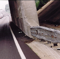
The function of the transition section is to gradually and smoothly stiffen a semi-flexible W-beam section having a 3-ftdynamic deflection as it attaches to a rigid, non-deflecting object such as a concrete bridge parapet or (anchored) concrete barrier to prevent pocketing.
1. Damage: Transition no longer reasonably functional.
W-beam element is not attached to rigid object.
W-beam is severely pocketed in advance of the rigid object.
2. Damage: Transition should function adequately under a majority of impacts.
Rail is flattened and bent/pushed out of line less than 12 inches; rail element is intact and securely attached to the rigid object.
3. Damage: Should not impair the transition's ability to perform.
Rail is flattened / pushed out of line less than 6 inches; rail element is intact and securely attached to the rigid object.
The traditional transition to concrete bridge parapets constructed before the 1990s used 3-ft, 1½-in post spacing for 25 ft in advance of the connection to the rigid object. When tested at a high speed, this design failed miserably.
Many designs meet the current testing requirements for high-speed facilities; for low speed facilities, the Texas DOT has developed a more economical[1]. All accepted transition designs incorporate four features:
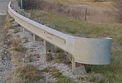
 Traditional transition.
 The whole treatment is typically 25 ft long but could be 18½ or 31½ ft. Although metal bridge railings may not be as rigid as concrete parapets, follow the same concept of a strong tension connection, gradual stiffening, and snag prevention.
Repair transitions that did not previously contain all the above features to current standards; if that is not practical, then provide the above features on high-type facilities. (A rail-to-post bolt is not required at the locations of any extra posts when an installation is not to a standard.) On lower type facilities, it may not be practical to include all of the features to their full extent, but all repairs should have a strong tension connection. Repairs should be conducted to correct the connection even if a transition is outside the normal limits of repair within a W-beam run or if it does not contain a strong tension connection.
Repaired Transition Checklist
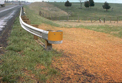
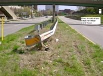
The function of the end treatment is to prevent serious injury to occupant when struck on the end and provide tension for the W-beam for side (traffic face) impacts.
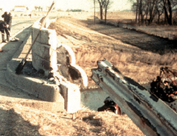
Over the years end treatments have developed from simply ending the W-beam run (probably with a "shovel" end section attached – with or without the end section, providing little tension but most importantly presenting a spear) to turn down systems (that provide tension and won't spear, but that could launch a vehicle) to stand-up "safe" end treatments. The two major types of stand-up end treatments are non-energy-absorbing and energy-absorbing.
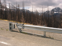
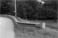
Non-energy-absorbing end treatment.
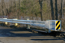
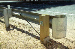
Energy-absorbing end treatment.
End treatments prevent serious injury either by being relatively soft for end-on impacts or using an energy-absorbing head slipped over the rail element to absorb the energy of the impacting vehicle by deforming the rail as it is forced into the head during shallow-angle, end-on impacts. For the stand-up end treatments, the tension function is provided by a cable attached to the rail element and anchored in the first post through a bearing plate and the post is placed in a foundation. Since the early 1990s, a strut ties post 1 together to post 2 to provide the needed resistance to the tension in the cable developed from a downstream impact.
1. Damage: End treatment no longer reasonably functional.
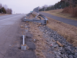
End treatment partially or fully destroyed and presents a blunt end Energy-absorbing system
End treatment partially or fully destroyed and presents a blunt end Non-energy-absorbing system
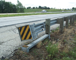
Energy-absorbing head off of rail– probably will not ride down rail but may create a spear.
Energy-absorbing end treatments depend on the column strength of the rail element to activate the energy-absorbing characteristic of the design. The rail element must be in a straight line to develop this strength. If there are dents in the rail element, even relatively small, near the impact head, then the system will probably not perform as desired for shallow-angle, end-on impacts. Replace the dented rail element.
2. Damage: End treatment should function adequately under a majority of impacts.
Post 1 is broken such that full tension is not developed for downstream hits; however, the impact head should absorb most of a vehicle's energy for shallow–angle, end-on impacts.
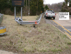
Neither the turndown nor the breakaway cable terminal (BCT) (see photos on the below) have been successfully crash tested for both a large vehicle (sedan or pick-up) and a small car. One should replace them with current standard hardware, even for minor damage. This is especially true for high-type facilities. Turndowns are easy to identify. The BCT looks similar to a MELT (Modified Eccentric Loader Terminal, see photo below), a stand-up end treatment that passed previous crash-test requirements and can be repaired when it incurs minor damage. The BCT has no strut between posts 1 and 2, standard strong posts for all posts beyond post 2, and bolts attaching the rail element to all posts.
Turndown is obvious.
Breakaway Cable Terminal (BCT) No strut between posts 1 and 2. Standard posts beyond post 2. Bolts attach rail to each post.
Modified Eccentric Loader Terminal (MELT) Strut between posts 1 and 2. All weak posts within system. No rail-to-post bolts except at post 1.
3. Damage: Should not impair the end treatment's ability to perform.
Post 1 is intact. Rail element is less than 12 inches out of line (non-energy-absorbing end treatment only).
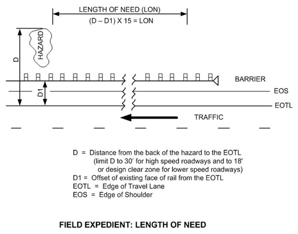
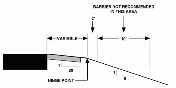
For a W-beam guardrail to adequately shield a serious hazard, the length of the W-beam guardrail must extend some distance upstream in advance of the hazard. If the W-beam guardrail is not long enough, then a vehicle can leave the roadway before it is beside the hazard and still reach the hazard the W-beam was intended to shield. This adequate distance in advance of the hazard is called the length of need (LON). Although a designer uses a special procedure to determine the LON, a simple field expedient procedure, shown in the sketch below, is to multiply the distance between the front of the W-beam and the back of the hazard (D-D1) by 15. If the back of the hazard is greater than 30 ft from the edge of the travel lane (EOTL) on a high-speed road, then 30 ft is a reasonable value for D. For lower speed roads, use a value of 18 ft (or the roadway's design clear zone[2] value, if known) instead of 30 ft.
The best end treatment is probably a properly constructed buried-in-backslope (BIB) end treatment. It provides full tension for the W-beam and eliminates the possibility of injury due to hitting the end since the end is buried. When a natural backslope is near where the agency plans to completely replace a damaged end treatment, a good option is to use a BIB for the repair (conditioned that no access is required behind the W-beam at this point).
When repairing or replacing a stand-up end treatment with a new stand-up end treatment, you should provide the LON. However, in the majority of situations, it is either unavailable or impractical to provide the LON. Although the non-energy-absorbing end treatments perform well to minimize the hazard of the end of the W-beam, their softness allows the vehicle to pass through and behind the guardrail, and without adequate LON, could reach the hazard the W-beam was intended to shield. An energy-absorbing end treatment has an additional capability beyond developing tension and not causing serious injury on end-on impact: for shallow-angle, end-on hits, it can absorb much of the vehicle's energy and either stop the vehicle within the system itself or slow the vehicle significantly such that any downstream impact should be less severe. Therefore, use energy-absorbing systems to repair or upgrade damaged end treatments if they do not have acceptable LON and satisfactory grading, as discussed below.
Many current crashworthy end treatments are proprietary and have been designed and engineered with unique details necessary to allow them to perform properly. For example, some posts in the installations have bolts connecting the rail to the post while others do not. Also, most designs have evolved to make them more effective as well as more economically competitive. Therefore, before beginning repair on these systems, or installing new as replacements, be sure you have the manufacturer's shop drawings and installation manual for the particular model on site.
Grading: All accepted end terminals (except the BIB) were tested on flat ground. Therefore, it is best to duplicate this condition in the field so the end treatment has the best chance of performing as intended. This is generally accepted as being provided when there is 5 ft of relatively flat ground (IV:10H or flatter) behind the first post of the system (and gradually tapered back to the existing cross section in advance of the end treatment), as shown below.
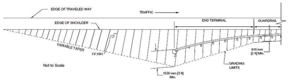
Recommended Grading Plan.
Source: Roadside Design Guide
The grading downstream of the end treatment should be available clear zone in accordance with the LON concept describe above. Also, because the posts of the system are designed to break off or bend upon end-on hits to allow the vehicle to continue down or through the system, ensure whatever posts remain after breaking or bending extend no more than 4 inches above the ground.
The previous recommendation to use energy-absorbing end treatments is re-emphasized because the 5 ft flat grading is seldom achievable in the field.
Guidelines for the Selection of W-beam Barrier Terminals developed by FHWA, provides additional information on the selection and performance of the different currently accepted end treatments. The CD-ROM (Publication Number FHWA-SA-06-19) containing these guidelines can be obtained from the FHWA Report Center. Fax requests to (301) 577-1421 or email requests to report.center@fhwa.dot.gov.
The Vermont End Terminal is a relatively inexpensive end treatment that provides both tension and a "safe" impact for lower speed (≤ 45 mph) facilities: (Additional information on this end treatment is available in the AASHTO Roadside Design Guide (RDG), chapter 8). Its use is also appropriate on a higher speed facility at the approach to a STOP sign. It uses a typical cable to develop the required tension and a radius W-beam element to prevent spearing. It is also fairly easy to construct.
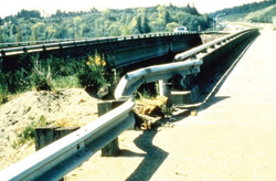
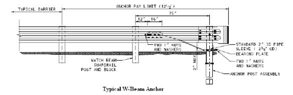
When an end treatment's only function is to develop tension, such as when used at the downstream end of a run of barrier (that is outside the clear zone of opposing traffic), an economical system is to simply attach the typical cable to the last rail element and anchor the cable in the last post that uses a steel foundation tube for resistance (see photo and figure on following page).
Repaired/Replaced End Treatment Checklist:
This chapter provides guidance on how to repair W-beam guardrail sections. Some critical actions you should take before the actual repair include:
The remaining portion of this chapter is divided into standard and transition sections, and end treatments
The following sequence is usually followed in repairing the standard or transition sections:
Make a final inspection before leaving the site. Complete the suggested checklist at each location to document the work.
Completed Work Inspection Checklist
(Standard Section and Transitions)
Date repair completed: _________________________
Repair completion inspected by:______________________________ (Signed)
The following steps are suggested for end treatments:
Because of the many possible options that repair/replace damaged end treatments, it is virtually impossible to give detailed instructions for their treatment. However, two items must be discussed.
Many different types of posts are used in the different end treatments, both generic and proprietary. Examples are:
Because of this variety, make a detailed inspection of the type in the existing installation. Replace damaged posts in an installation that is only to be partially repaired with the same type of the original posts. However, several manufacturers have developed steel posts that facilitate repair – be sure to check with each manufacturer for approved variations and mixing of post types before using a post type different than the damaged one(s).
To repair or replace any proprietary types of end treatments, it is imperative that crews have the manufacturer's shop drawings and installation manual on site during repairs. Installation manuals also contain guidance for repairing damaged installations and can be used on generic installations as well, such as removing the wood stub left in a foundation tube.
Completed Work Inspection Checklist (End Treatments)
Date repair completed: _________________________
Repair completion inspected by: ______________________________(Signed)
All agencies should maintain work records of maintenance performed. If your agency has an existing system for keeping track of maintenance work, then use it to record work to repair the guardrail, record the parts used, when the repair was made, and verify that work was checked for correctness.
If your agency does not have a complete record system, then consider the following suggestions:
Damage inspection Report – New York State DOT
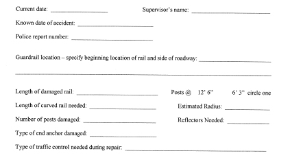
Calculating Guardrail Radius (to complete form above)
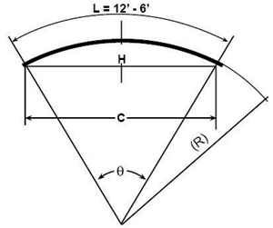
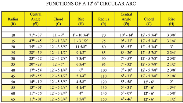
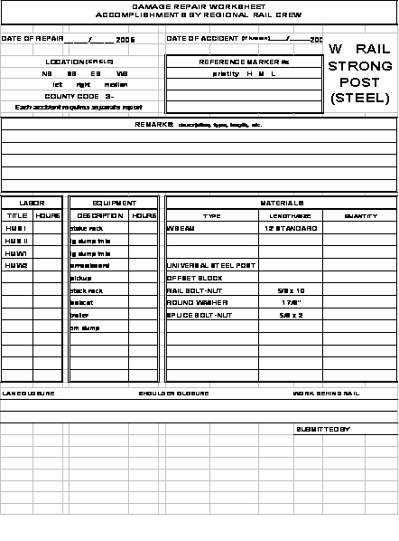
Typical elements of the W-beam guardrail (a standard 12-ft, 6-in rail length is assumed; if an agency allows a 25-ft rail length, then make appropriate adjustments) include the following:
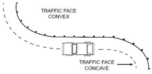
 Traffic
W-Beam with Wood Offset Block on Wood Post
Traffic
W-Beam with Approved Offset Block on Steel Post
Traffic
W-Beam with Steel Offset Block on Steel Post
| Item | Compute | Number needed |
|---|---|---|
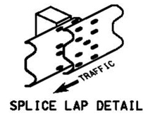
W-beam galvanized steel rail sections 12-ft, 6-in-long, desirably punched @ 3ft, 1½ -in spacing |
Tally # of damaged Sections @ 12ft, 6 in |
|
⅝-in by 1¼ -in-long splice bolts with nuts |
(# sections x 8) + 8 |
|
⅝–in rail-to-post bolts with recess nuts and round washers for connecting rail to post and block |
(# sections x 2) + 1 |
|
6-ft , 0-in posts* |
(# sections x 2) + 1 |
|
Offset blocks |
Same as # of posts |
|
For wood block on wood post: 10
16d galvanized nails |
2 x # of offset blocks |
|
For steel block on steel post: 12-in W-beam back-up plate |
Same as # of sections |
|
For steel block on steel post: ⅝ -in by 1½ -in hex-head bolts to connect block |
2 x # of offset blocks |
|
Guardrail-mounted delineators |
Same as # of sections |
|
Object (hazard) markers |
1 for each end |
* If there is not adequate soil support behind the posts, use 7 ft or longer posts.
This list indicates an exact number of parts. Be sure to take into account additional numbers of each part for damage, loss, etc.
A detailed list like this is not appropriate for end-treatment repair/replacement. The proprietary manufacturers' installation manuals contain bills of material for each model of their products. Check these when conducting a complete replacement installation or for the appropriate quantities based on the amount of repair/replacement.
The following is a listing of equipment and tools that will be needed for guardrail repair. There are two lists: the first is from a typical state highway agency truck; and the second is from a typical guardrail contractor truck. Make sure you comply with OSHA or your local regulations when using this equipment.
Supervisor Truck Supplies |
|
⅜-in drive ratchet and socket set (end treatments have small nuts and bolts) |
¾-in drive ratchet and socket set (bridge connections and anchor terminals) |
½-in drive ratchet and socket set with 3-in and 10-in extensions |
7/16 to 1⅛" sockets |
5 to 1¼" bell sockets |
4-in to ½-in drive sockets |
Four - splice pins, 2 pinch bars / pry bars |
Open end and box wrench set 5/16 to 1¼ inch |
Two ½-in impact wrench |
Two 5/16-in impact sockets |
Two 1⅛-in impact socket |
Three 1¼-in impact bell socket |
Two 1¼-in Impact Deep Bell Socket |
|
One 15-in adjustable wrench |
One 20-in adjustable wrench |
Four vise grip pliers |
Two 4-lb hammers |
One 18 lb sledge hammer |
One 10-lb sledge hammer |
Two flat shovels |
Two round shovels |
Two post hole digger |
Two digging bars |
One post puller |
Cut-off saw, extra blades |
Chain saw, bar oil |
Mix oil for saws |
2- or 3-gal mix gas can |
2 5-gal gas cans |
Hilti concrete drill set |
Hilti ½, ⅝, ⅞, 1-in bits |
3 7/8–inch-hole saws |
Epoxy |
Long heavy-duty jumper cables |
Ink markers |
Acetylene torch set |
Two chisels |
3500-watt generator |
Two 100-ft electric cords |
Two1/2-in VSR drills |
Two 1-in step bits |
Paint & cold galvanizer |
Penetrating oil / spray |
Two- Line levels |
String line |
Line pins |
200-ft steel tape |
G/R Standards and Specifications |
Construction Log Book |
Accident Investigation Reports |
Two Pull binders |
Maintenance of Traffic Standards |
Work zone signs & stands |
STOP / SLOW paddles |
Cones |
Hard hats, safety
vests, safety glasses, gloves, |
MSDS Manual, Hazard Communication, Safety Manuals |
First-aid kit |
Blood-Born Pathogen Kit |
First-Aid Reports |
Wasp and bee spray |
5-gal water cooler |
Quantity sheets |
Respirators |
Camera |
Clipboard |
Timesheets |
Cell phone |
Credit cards |
Guardrail-mounted delineators |
Object Markers |
Post Pounder Truck / Rail Truck |
|
Add to Supervisor Truck Supplies: |
|
Truck-mounted post pounder – holds 30 posts – grease gun |
|
Air compressor, 92 CFM |
Two air hoses |
Hydraulic cylinder (pulling) |
Three chains |
Canvas strap for lifting |
One 60-lb jack hammer |
Two vehicle battery chargers |
Two Dewalt 18-volt wrenches |
Foreman Truck Supplies |
|
⅜-in drive ratchet and socket set (end treatments have small nuts and bolts) |
|
¾-in drive ratchet and socket set (bridge connections and anchor terminals) |
|
½-in drive ratchet and socket set with 3" and 10-in extensions |
|
7/16-in to at least 1⅛inch sockets |
One 20-in adjustable wrench |
Five 1¼-in bell sockets |
110-lb sledge hammer |
4½-in drive sockets |
118-lb sledge hammer |
Four splice pins |
115-in adjustable wrench |
Four vise grip pliers |
Combo open end and box wrench set 5/16 to 1¼ inch |
Two 4lb. hammers |
|
Post puller |
Chain saw |
Two flat shovels |
Cut-off saw |
Two round shovels |
Saw blades |
Two digging bars |
Mix oil for saws |
Two- post-hole diggers |
Bar oil |
Long, heavy-duty jumper cables |
Two or three gallon mix gas cans |
Two 5-gal gas cans |
Acetylene Torch Set |
Ink markers |
3500-watt generator |
Two 100-ft electric cord |
Two ½-in VSR drills |
Two 1-in step bits |
Three ⅞-in hole saws |
Two ½-in impact wrenches |
Two ½-in impact wrenches |
Two ½-in impact wrenches |
Four swivel sockets |
Two 5/16-in impact sockets |
Two 1⅛-in impact socket |
Three 1¼-in impact bell socket |
Two 1¼-in impact deep bell sockets |
HILTI concrete drill set with bits ½, ⅝, ⅞, 1 inch |
Clipboard, time sheets, quantity sheets |
Epoxy |
Dust mask |
Line levels |
Construction Log Book |
Line pins |
G/R Standards and Specifications |
String line |
Cell phone |
Credit cards |
Paint & cold galv. |
Accident Investigation Reports |
Two pull binders |
Camera |
Proper work zone signs & stands |
200-ft steel tape |
STOP / SLOW paddles / cones |
First-aid kit |
Blood-born pathogen kit |
First-Aid Reports |
M.O.T. Standards |
5 gal water cooler |
Penetrating oil / spray |
Wasp and bee spray |
|
MSDS manual, hazard communication, safety manuals |
|
Hard hats, safety vests, safety glasses, gloves, hearing protection |
|
General guidelines:
Repairing cosmetic damage to guardrail installations--Should your agency want to repair the very minor type of damage mentioned earlier in this handbook, the actual repair (which may only be painting or minor straightening of a dented rail) should not require more than 30 minutes to 1 hour.
Repairing damage that still permits the guardrail to function --When the inspection of the damage at the site indicates:
Or other conditions exist that permit routine scheduling of the repair (rather than emergency repair), plan for 1 to 2 hours of repair time, plus traffic control, inspection, and recording.
Repairing major damage requiring prompt attention--When the guardrail damage is extensive, such as four or more posts are knocked out or several rail beam sections are broken, plan on one half day time requirement, including the traffic control setup, inspection, and recording.
FOR AGENCIES WITH MAINTENANCE MANAGEMENT SYSTEMS THAT GIVE A MORE DETAILED TIME BREAKDOWN, USE THAT TO ESTIMATE TIME.
The crew size will depend upon the extent of the damage and the needs for traffic control. Two workers and a person in charge should be enough to repair minor damage where the guardrail is allowed to remain assuming the guardrail would function satisfactorily while the repair was scheduled. This assumes the work involves only a few posts or rail beam sections. When four or more posts are involved, or more than two rail beam sections are to be replaced, expect to need a crew of four. If a wide range of power-assisted tools is available, then a crew of three should work well.
Traffic control crew needs are as follows:
IF YOUR MAINTENANCE MANAGEMENT SYSTEM GIVES MORE DETAILED CREW SIZE INFORMATION BY WORK TASK FOR GUARDRAIL REPAIR, THEN USE THAT CREW SIZE ESTIMATE.
W-beam guardrail repair log
 \
\
The following Instructional and Informational Memorandum can be found at: http://www.extranet.vdot.state.va.us/locdes/electronic%20pubs/iim/IIM220.pdf
VIRGINIA DEPARTMENT OF TRANSPORTATION
GENERAL SUBJECT: GUARDRAIL REPAIR, REPLACEMENT AND UPGRADE GUIDELINES |
NUMBER: IIM–LD–220.2 MM – 327 CD – 2003 – 4 |
SPECIFIC SUBJECT: |
DATE: NOVEMBER 21, 2003 |
SUPERSEDES: IIM–LD–220.1 TE – 305 CD – 2001 – 9 |
|
LOCATION AND DESIGN DIVISION APPROVAL: Mohammad Mirshahi, P.E. Approved November 12, 2003 |
SCHEDULING & CONTRACT DIVISION APPROVAL: W. Byron Coburn, Jr., P.E. Approved November 19, 2003 |
MOBILITY MANAGEMENT DIVISION APPROVAL: Raymond J. Khoury, P.E. Approved November 20, 2003 |
ASSET MANAGEMENT DIVISION APPROVAL: James R. Smith, Jr. Approved November 21, 2003 |
CURRENT REVISION
EFFECTIVE DATE
POLICY
During routine maintenance projects and/or contracts of any roadway, all guardrail shall be reviewed, deficiencies identified, costs budgeted, and schedules set for replacement or upgrading to ensure that all existing guardrail meets current VDOT Standards. During these reviews if the guardrail is found to be more than 75 mm (three inches) lower or 75 mm (three inches) higher than current Standard requirements, then replacement or resetting shall be scheduled as soon as possible. For strong post guardrail (Standard GR-2) no metal blockouts are to be replaced in-kind or installed new, and no washers will be used other than those for the last 15.2 meters (50 feet) of a trailing end anchorage.
GUARDRAIL TERMINALS – DAMAGED AND SUBSTANDARD
BCT's had concrete footings for the first two posts, did not have the metal strut at ground level between the first two posts and all posts were not breakaway.
Completely replace BCT's with new NCHRP 350 approved terminals whenever they are damaged or if they are within the limits of a construction or maintenance project/contract.
The MELT provides a 1.2-meter (4-foot) offset, a 1.5-meter (5-foot) flat area behind the first post and a metal strut at ground level between the first two wooden breakaway posts.
If the MELT (Standard GR-7) is improperly installed or when damage includes the nose assembly and first two posts, replace with new NCHRP 350 approved terminals (revised Standard GR-7) such as the SRT-350, FLEAT 350, REGENT or other approved NCHRP 350 product. When replacing substandard GR-7 terminals, make sure that the section of rail and posts adjoining the new terminal installation is at the proper height.
All turned-down strong post terminals (run-on locations) should have already been removed from roadways on the National Highway System. Any that have not been removed shall be removed immediately.
When these terminals that may remain on non-NHS roadways are damaged, they shall be replaced with NCHRP 350 approved terminals.
Since no weak post terminals have been approved in accordance with NCHRP 350 for use in run-on locations, any of these terminals that are damaged shall be replaced with NCHRP 350 approved strong post terminals incorporating the appropriate transition required between a strong post terminal and weak post guardrail (in accordance with VDOT Road and Bridge Standards), regardless of the design speed of the roadway.
Any weak post run-on terminals within the limits of a construction project, maintenance project and/or contract shall be upgraded as part of the project.
For run-off locations, turned down terminals incorporating a concrete anchor (Standard GR-8, type I or II) are acceptable, regardless of the design speed of the roadway; however, the Type I and II terminals shall be outside of the clear zone of opposing traffic on two-way roadways. This includes existing installations in locations with design speeds greater than 70 km/h (45 mph) for which new installation of weak post guardrail must be in accordance with the new approved TL-3 weak post design.
Existing GR-6 installations that are not NCHRP 350 compliant (in accordance with current VDOT Standards) should be evaluated to ensure the following:
- Proper Height per current standards -
Where existing GR-6 Terminals were installed with the height of rail following the ground line at a height of 27" to 28", this installation method caused the terminals to be low, both in front of and behind the ditch line. These low installations may allow an errant vehicle to vault over the top rail and go behind the guardrail, failing its intended protection from hazards.
- The end anchorage is sufficiently buried in the slope 0.3 m (min. 1 foot cover).
Repair or replacement of either of these situations shall be to current VDOT Standards.
FIXED OBJECT ATTACHMENTS (FOA'S)
W-BEAM GUARDRAIL
When substandard GR-8 is damaged, the extent of damage should govern repair/replacement. If the total run of guardrail is 60 meters (200 feet) or less, the entire run shall be replaced with the latest GR-8 design (which meets NCHRP 350 Test Level 3 criteria) or if the particular site conditions are appropriate a Standard GR-2 or GR-3 system can be used.
For substandard sections of GR-8 guardrail that are longer than 60 meters (200 feet), if more than 60% of the entire run has been damaged, or does not meet current Standards, the entire run shall be replaced with the latest GR-8 design or if the particular site conditions are appropriate a Standard GR-2 or GR-3 system can be used.
If less than 60% of the entire run has been damaged, the damaged section should be replaced with the latest GR-8 design or if the particular site conditions are appropriate a Standard GR-2 system can be used.
When either of these designs is used, the proper transitions MUST be incorporated. Transitions to the new height, splice locations and backup plates for the GR-8, and for the GR-2 transitions from GR-8, 8A, 8B to the GR-2 must be done in accordance with current Standard designs. The latest GR-8 design can be used even for speeds greater than 70 km/h (45 mph).
Existing weak post W-beam, not meeting NCHRP 350, that is within the limits of a reconstruction or maintenance project shall be upgraded to the new Standard design. When resetting or reusing rail, the height of the rail shall be installed to meet the current VDOT Road and Bridge Standards.
All Standard GR-1 guardrail should be identified and replacement schedules set for all roadway systems so that appropriate funding can be budgeted for upgrades. Standard GR-1 on any roadway within the National Highway System (NHS) shall receive first priority for upgrading as soon as possible.
Existing strong post guardrail (Standard GR-1) and end terminals within the project limits of any project/contract should always be replaced with a new NCHRP 350 approved system.
When damaged, the extent of damage should govern repair/replacement. If the total run of guardrail is 60 meters (200 feet)+ or less, the entire run shall be replaced with strong post (Standard GR-2) guardrail.
For sections of guardrail that are longer than 60 meters (200 feet), if more than 60% of the entire run has been damaged, the entire run shall be replaced with strong post (Standard GR-2) guardrail. If less than 60% of the entire run has been damaged, the damaged section should be replaced with strong post (Standard GR-2) guardrail.
When damaged, replace in kind in accordance with current standards; NO STEEL BLOCKOUTS shall be used. Rectangular washers shall be removed on a regular run of guardrail with the exception that washers should still be retained or added to the last 15 meters (50 feet) of a trailing end to provide end anchorage on the run-off end of a one-way roadway. Discard the steel blockouts and use routed 150x150x360 mm (6"x6") wood or composite blockouts. The wood and composite blockouts can be used interchangeably within a single run of guardrail for both NEW or repair,replacement and upgrades. When existing 150x200x360 mm (6x8) wood or composite blockouts are replaced during repairs, the blockouts shall include routing to prevent blockouts from rotating. When wood posts with wood blockouts are used, they should have TWO nails (one on each side) to prevent rotation of blockouts.
When posts are removed and meet current specifications for reuse, they should be reused only if they are 1.75 m (5' 9") or longer with Standard wood or composite blockouts. When resetting rail, the posts shall be removed and the holes backfilled prior to reinstalling the posts. The height of the rail should be measured to ensure it meets the current VDOT Road and Bridge Standards.
CABLE GUARDRAIL (STANDARD GR-3) DAMAGE
As resources (funding, staff, and equipment) allow, the following best practices are recommended as part of a regular maintenance program. Conduct an annual or biannual review of all W-beam guardrail in a jurisdiction. Keep a record of the inspection by date and person carrying out the inspection. This will be helpful in the event of a lawsuit resulting from a crash. Look for the following features:
A useful tool for managing this asset is an inventory (with possibly a rating system) of existing W-beam barrier, indicating the type of W-beam (post and offset block material, rail material) and the type of end treatment (model name and materials). The inventory is also useful in setting priorities for improvement projects. The following is an example inventory system being developed by New York State DOT. For additional information on this inventory system, contact NYSDOT's Transportation Systems Maintenance, 50 Wolf Road, Albany, NY 12232; phone: 518-457-6435.
New York State Dot Guardrail Inventory System Report.
The concept of clear zone is an approach to minimize the number and severity of crashes involving vehicles running off the road. Simply stated, it is a traversable area that starts at the edge of the traffic lane and extends laterally a sufficient distance to allow a driver to stop or return to the road before encountering a hazard or overturning. The traversable area would be considered safe, if there were no fixed objects, unless they are breakaway, and if the roadside geometry (either the fore slope, back slope, or ditch) was flat enough that a vehicle could safely traverse the area without tipping and rolling over. Roadside safety features include breakaway sign and light posts, and traversable drainage structures. Curbs are not considered a roadside safety feature since they can be easily mounted by errant vehicles; hence, their presence does not alter how clear zone is measured.
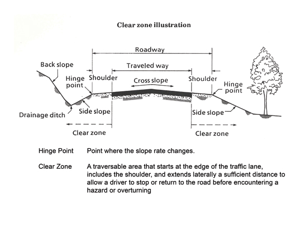
A safe traversable slope can be either a recoverable slope or a non-recoverable slope with a clear run-out area at the bottom. A recoverable slope is a slope on which a motorist may, to a greater or lesser extent, retain or regain control of a vehicle and recover or stop. Slopes 1:4 (Vertical:Horizontal) or flatter are generally considered recoverable. A non-recoverable, traversable slope is a slope which is considered traversable but on which an errant vehicle will continue to the bottom. Embankment slopes from 1:3 and 1:4 may be considered traversable but non-recoverable if they are smooth and free of fixed objects. A clear run-out area is the flatter area at the toe of a non-recoverable slope available for safe use by an errant vehicle. Slopes steeper than 1:3 are not considered traversable and should not be found in the clear zone.
The objective of roadside safety is to provide and maintain as much clear zone as practical. The design clear zone is the minimum width to be provided on a project and is dependent upon speeds, the roadside geometry, and traffic volumes. Further details on clear zone can be found in the Roadside Design Guide.
[1] Design can be seen at ftp://ftp.dot.state.tx.us/pub/txdot-info/cmd/cserve/standard/roadway/mbgtl205.pdf
[2] See Appendix D for description of clear zone.

