U.S. Department of Transportation
Federal Highway Administration
1200 New Jersey Avenue, SE
Washington, DC 20590
202-366-4000
Download Version
PDF [9.16 MB]
Notice
This document is disseminated under the sponsorship of the Department of Transportation in the interest of information exchange. The United States Government assumes no liability for its content or use thereof.
The contents of this report reflect the views of the author, who is responsible for the facts and the accuracy of the data presented herein. The contents do not necessarily reflect the official policy of the Department of Transportation.
This report does not constitute a manual, handbook, standard, specification, or regulation.
The United States Government does not endorse products or manufacturers. Any trademarks or manufacturers’ names that appear herein do so only because they are considered essential to the objective of this document.
1. Report No. FHWA FHWA-SA-09-024 |
2. Government Accession No. |
3. Recipient’s Catalog No. |
|||
4. Title and Subtitle Maintenance of Drainage Features for Safety, A Guide for Local Street and Highway Maintenance Personnel |
5. Report Date July 2009 |
||||
6. Performing Organization Code |
|||||
7. Authors FHugh W. McGee, P.E., Daniel Nabors, P.E., and Timothy Baughman, P.E. (editors). |
8. Performing Organization Report No. |
||||
9. Performing Organization Name and Address |
10. Work Unit No. |
||||
Vanasse Hangen Brustlin, Inc. 8300 Boone Boulevard, Suite 700 Vienna, VA 22182-2626 |
11. Contract or Grant No. DTFH61-05-D-00024 |
||||
12. Sponsoring Agency Name and Address Office of Safety |
13. Type of Report and Period Covered Final Report
|
||||
14. Sponsoring Agency Code |
|||||
15. Supplementary Notes: The FHWA Office of Safety Contract Task Order Manager was Ms. Karen Timpone. The document was originally prepared by staff at FHWA as a revision to the 1990 edition of the same title FHWA-RT-90-005. Those identified as authors above provided additional material and served as technical editors. |
|||||
16. Abstract This guide was prepared to help local road agency maintenance workers understand the importance of maintaining and upgrading drainage features on their road system. Storm water that stands or ponds on the road surface and shoulders can contribute to crashes. It can cause hydroplaning under water conditions and skidding under icing conditions. Water run-off can deteriorate the shoulder, sideslopes, and reduce the effectiveness of safety hardware (guardrails, sign posts, etc.) This guide identifies typical drainage problems and suggests corrective measures to improve safety. |
|||||
17. Key Words Vegetation control, safety, maintenance, sight distance |
18. Distribution Statement No restrictions. This document is available to the public through the National Technical Information Service, Springfield, VA 22161. |
||||
19. Security Classif. (of this report) Unclassified |
20. Security Classif. (of this page) Unclassified |
21. No. of Pages: 38 |
22. Price |
||
Form DOT F 1700.7 (8-72) - Reproduction of completed pages authorized
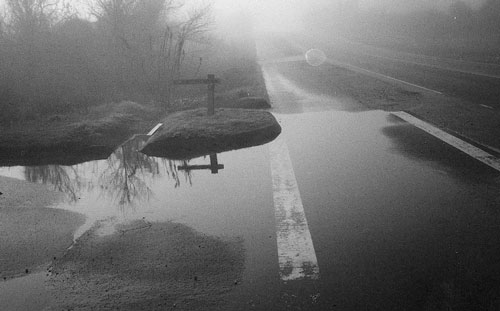
Safety on streets and highways, bicycle trails, and sidewalks is essential to motorists, bicyclists, and pedestrians. Drainage systems that remove storm water run-off from streets and highways are an integral feature of a safe system. Water that remains on the roadway(1) surface can contribute to vehicle hydroplaning. In winter, standing water can freeze and cause skidding.
(1) In the context of this guide, the roadway includes the travel lanes and shoulders, if any. Streets and highways are considered roadways or roads. The travel way is that portion of the roadway for vehicle travel.
The curbs, gutters, channels, and ditches that carry the run-off away from the roadway can have a serious effect on an errant motorist or bicyclist when not designed and maintained correctly. Erosion along the roadway can also contribute to the severity of a crash or inundate crashworthy systems such as breakaway sign supports. Even headwalls, pipe ends and grates on drop inlets and pipe openings need to be safety treated when they are within the area an errant motor vehicle or bicycle can reach.
Maintaining roadway drainage is important for safety and for ensuring the long life of the roadway by:
This guide is intended to help local road agency maintenance workers understand the importance of maintaining and upgrading drainage features on their road system to avoid an unsafe condition. Its purpose is to highlight common roadway drainage problems that can cause an unsafe condition and suggest inspection methods and corrective action. This guide is not intended to be a design guide. Readers may want to contact their State Local Technical Assistance Program (LTAP) for more details on drainage design.
There are many factors affecting safety on local streets and highways, and one of these is how drainage—the run-off of water from the pavement and shoulder—is treated.
The primary objective in treating drainage is to ensure that safe operating conditions exist on the roadway. This is done by removing storm run-off, providing for snow removal and reducing the ability for ice to form on roadways and bridges. Additionally, the drainage systems used on the roadway should not be hazardous or reduce the crashworthiness of other systems, such as breakaway signs and guardrail.
Also included as part of this objective is the safe design and maintenance of drainage features, such as travel way and shoulder surfaces, side slopes, drop inlets, pipe ends, ditches, headwalls, safety grates, culverts, gutters, roadside and median barriers and other features that restrict the flow of water or removal of snow.
Drainage factors that affect safety on the travel way of streets and highways include:
(2) Ponding refers to water collecting on the pavement or shoulder that is deteriorated. Standing water refers to water collecting on the surface due to insufficient cross slope or backup in the drainage system.
Travel ways are generally designed to provide sufficient cross slope to facilitate storm run-off; however both traffic and maintenance activities can and often do affect the original cross slope of the roadway surface. Traffic, particularly heavy truck traffic, can cause wheel ruts in the pavement surface.
Water ponding in wheel ruts.
Rutting is caused by the wear or movement of the bituminous pavement to the sides of the wheel path. Rutting usually runs parallel to the centerline of the roadway. When wheel ruts are noticeable, they are generally deep enough to pond sufficient water to initiate hydroplaning.
Another pavement condition, often referred to as shoving, can occur where vehicles frequently stop, such as at intersections. Shoving is most common at stop locations, particularly on steep downgrades. Shoving results in a series of ridges running across the roadway. The ridges can retain water and are hazardous even when dry because they cause the wheels of a vehicle to bounce, reducing wheel contact with the roadway surface and decreasing braking ability.
Ponding or standing water in the travel way may also cause some drivers, bicyclists, or pedestrians to divert from their desired path. Storm drains or drop inlets that have collected debris, such as leaves, can cause ponding during and after storms. Both motor vehicle and bicycle operators may choose to avoid going through the water by encroaching on the opposing lane, thus endangering themselves and opposing traffic.
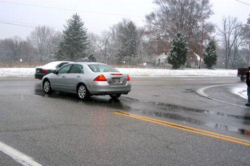
Water standing in the roadway.
In sections of the travel way where run-off drains directly onto the shoulders (where there are no curb and/or gutters), water may collect along the edge of the travel way. Water on a portion of roadway can result in drivers losing control of their motor vehicle, particularly when braking in an emergency. This can happen when the inside tires are in contact with roadway surface while the braking ability of the outside tires is hindered by the water.
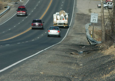
Water can pond on the outside edge of the travel way surface when debris, particularly aggregate and soil on turf shoulders, builds up. As debris accumulates on the shoulder, it raises the level of the edge, and eventually hinders run-off from flowing into side ditches.

Water ponding at the edge of roadway.
Water ponding on the edge of the pavement contributes to the deterioration of the pavement edge and the rutting of stabilized soil supporting the pavement edge, which can result in additional safety hazards. Edge drop-offs and shoulder scour are often caused when water is trapped at the pavement edge by the build-up of debris and vegetation growth.
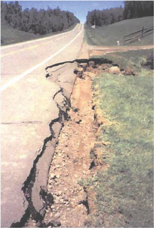
Deterioration of pavement edge and shoulder due to poor drainage.
Partial overlays and pavement repairs can result in water being trapped and retained on the travel way surface. Partial overlays, either to correct shoulder deterioration or widen the roadway surface, result in a pavement edge where the overlay stops. Depending on the size of aggregate in the overlay mix and the effort taken to feather the lip into the existing pavement, water can be retained on the travel way. When the lip is along the wheel path, the thin layer of retained water can initiate hydroplaning, reduce braking ability or freeze and contribute to skidding.

The edge of this partial pavement overlay is causing water to be retained on the travel way surface.
The area along the side of the roadway is also affected by run-off. Ditches and side slopes (either foreslope or backslope) are affected by storm run-off and maintenance activities. Motor vehicles and bicycles occasionally run off the roadway, but when the side slopes are relatively flat (1 vertical:10 horizontal [1V:10H] slope or flatter) and well graded (free of erosion scars) and ditches maintained with traversable side slopes, most drivers can recover control of the vehicle and return to the roadway or come to a safe stop.
One of the reasons that run-off-the-road errant vehicles may not be involved in a severe crash is safer shoulders and forgiving roadsides. Many roadways are designed to allow run-off to travel across the shoulders and be collected in a ditch or channel or flow down the side slope and seek a natural channel.
Drainage ditches are common on roadways when curbs are not used to channelize storm run-off. There are also cut-off ditches used along the travel way to prevent run-off from adjacent land flowing onto the travel way.
Drainage ditches should be designed so a vehicle leaving the roadway can cross over them without the vehicle overturning, being abruptly stopped or causing the driver to lose control.
Drainage ditches over which a motor vehicle can safely drive are called traversable. Design criteria for traversable drainage ditches are provided in the current edition of the Roadside Design Guide (see references at the end of this guide).
Ditches need to be cleaned on a regular basis to prevent them from silting up and forcing water back onto the travel way surface or into the subbase of the pavement.
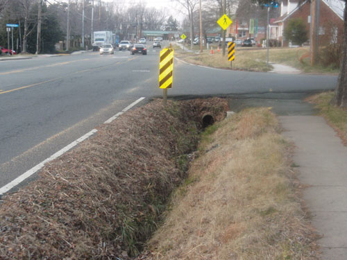
A traversable drainage ditch such as this provides space for vehicle recovery.
A non-traversable drainage ditch such as this is a safety hazard.
Earth ditches are subject to erosion. The ruts and deposits of silt and debris can change the shape of the ditch, resulting in sections that are no longer traversable or forgiving. Additionally, maintenance activities, such as cleaning ditches, can result in creating a non-traversable ditch.

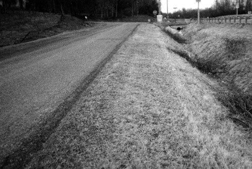
This regraded earth shoulder and ditch has a steep backslope which makes it non-traversable; if right-of-way is available the backslope should be made less steep.
Side slopes along the travel way may also become eroded, particularly when ditches silt up. The steeper side slopes (1V:3H and 1V:4H) that are marginally traversable become hazardous when they develop erosion channels that can trip or snag a tire.
In addition to ditches and side slopes, incorrectly maintained drop inlets, pipe ends, culvert ends, head walls, and other drainage features located adjacent to the roadway may be potentially hazardous.
Pipe ends, culvert wing walls, and headwalls adjacent to the roadway are potentially hazardous when they extend above the surrounding ground. These features are rigid objects that can snag the undercarriage of a vehicle leaving the roadway or initiate vehicle rollover.
Many of the older drainage features were built above the ground. These features are rigid objects that can cause serious injury if hit. Current practice provides for traversable ends, extension or relocation of the ends far enough away from the roadway to reduce the risk of a crash or use of a barrier system to shield road users from a hazardous location.
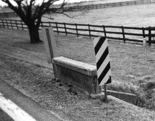
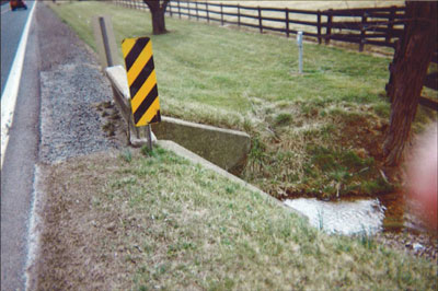
This headwall is a roadside obstacle and should be replaced as soon as possible.
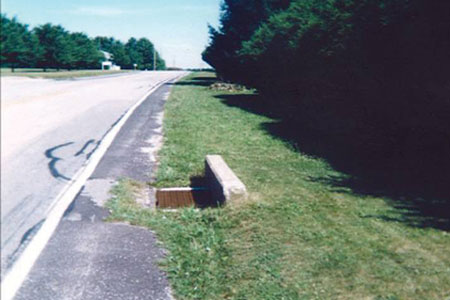
The headwall is sticking up almost a foot in a relatively flat recoverable area. It can snag a vehicle and bring it to an abrupt stop or cause it to overturn.
Even traversable drainage features can become hazards when storm run-off or maintenance operations, such as dressing side slopes, result in the feature extending above the surrounding ground. These features are rigid objects that can snag the undercarriage of a vehicle leaving the roadway or initiate vehicle rollover.
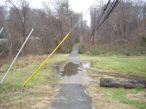
This water ponding on a ped/bike path could have been avoided by proper grading of the path.
The safety of pedestrians and bicyclists can also be jeopardized by poor drainage in the travel way, shoulder, or paths. While these users are more able to avoid or compensate for standing water or ice in their path, maintenance activities and relatively low-cost improvements can prevent drainage problems and improve the safety for these users.
The drainage problems discussed in the previous section can directly cause or contribute to crashes. As an example, drainage features that fail to remove run-off because they are too small or are clogged and pond water on the roadway can cause hydroplaning or force drivers to leave their lane. Additionally, other drainage features which do not have anything to do with causing a crash can significantly contribute to the severity of the crash, such as an errant vehicle striking a culvert headwall.
It is important to identify these potentially hazardous situations as soon as possible. Some of these conditions may have been in existence for quite some time, while others may have recently developed as a result of a storm or change in weather conditions. For areas of the country that are subject to freezing, the spring thaw frequently reveals pavement, shoulder and roadside deterioration.
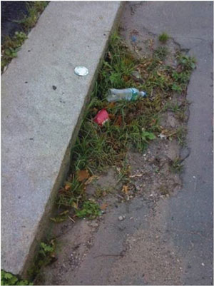
A clogged drain can easily be detected during a field survey.
Drainage problem locations can be identified in several ways:
FIELD INSPECTION CHECK LIST
(CHECK FOR THE FOLLOWING CONDITIONS)
1. Rutting or shoving of pavement surface.
2. Discontinuity of surface level between the pavement and shoulder (shoulder drop-off).
3. Accumulation of earth or debris on shoulder.
4. Existence of erosion channels on ditch side slopes.
5. Silt or debris accumulation in ditch.
6. Headwalls and drainage structures that are not flush with the ground.
7. Damage to drainage structures, such as crushed culverts.
8. Grates with wide openings parallel to the roadway that can trap bicyclists.
9. Drains blocked by soil and debris.
10. Side slopes that have steepened due to erosion.
11. Erosion around all roadside structures such as headwalls, sign posts, and guardrail posts.
12. Drainage structures within clear zone that are not traversable or protected by suitable barrier system.
There are many drainage features on and along streets and highways. They include the curbs and gutters, drop inlets and catch basins, pipes, culverts, and ditches needed to collect and carry storm drainage away from the road. When these features are located on a roadway or are adjacent to it where a vehicle, bicycle or pedestrian has a chance of traveling over or into the feature, the drainage feature should be designed for safety.
Drainage features that have been designed for safety, crash tested, and found to operate safely under the design conditions are usually referred to as crashworthy. Basically, crashworthy means a highway feature or appurtenance will not stop a vehicle abruptly, cause the driver to lose control or cause the vehicle to roll over.
This section describes corrective measures that can be taken to mitigate the effects of an identified drainage problem that affects safety.
Side slopes, both cut and fill embankments, and ditch sides, are usually constructed in the ranges of 1V:3H to lV:6H (or 1V:8H in relatively flat areas). Steeper slopes pose greater safety risk to motor vehicles traveling across or down them. These steeper slopes are also more difficult to maintain.
Side slopes of 1V:4H or flatter are commonly accepted as safe side slopes. These slopes are traversable and recoverable. Drivers of errant vehicles can steer, brake, and recover from a run-off-the-road mistake.
Side slopes between 1V:3H and 1V:4H offer marginal safety for vehicles. These slopes are called traversable, but non-recoverable and vehicles will travel beyond the bottom of the slope; therefore, a recovery area should be provided at the bottom of the embankment.
All slope surfaces should be smooth, free of fixed objects, and free of snagging features, such as headwalls. Vehicles traveling down slopes are difficult to control and may strike, roll over or drop into a feature such as a pipe end, which can cause a vehicle to halt abruptly, become unstable and roll over, or strike the back of the slope.
Erosion scars on a side slope can also initiate vehicle instability by tripping the vehicle’s wheels and initiating overturning. Therefore, eroded slopes should be graded and seeded. When rip rap is used to control and spread the flow of water, it should have shallow inverts and be placed flush with the existing ground. Additionally, the roadside conditions should be checked to determine why erosion is taking place and the problems resolved.
Side slope erosion can cause rollovers.
Soil erosion can have a detrimental effect on safety appurtenances, such as guardrail, sign supports, and highway light supports. The deposit of several inches of eroded soil or the erosion of several inches can significantly reduce crashworthy characteristics.
Soil deposited around breakaway appurtenances can cause them to malfunction or simply not break away. Additionally, run-off can result in the erosion of soil around these safety features, reducing their operational characteristics, such as deflection on impact rather than breaking away. This can cause a vehicle to roll over or abruptly stop.
Eroded and silted areas around barrier posts, breakaway sign supports and highway light supports should be restored to the desirable ground level and seeded. If the area continues to erode, bituminous overlays may be considered.
Desirably, drainage channels should not end near a safety feature or drain adjacent to one where soil can erode around it.
Pipes and culverts may have headwalls or special pipe end sections. Headwalls tend to channel water around their edges and can cause erosion gullies to develop. The storm flow from the pipe or culvert can also erode the sides of a paved channel or the bottom of a graded channel. If these water channels erode, they can create gullies on the side slopes that can trip the wheels of an errant vehicle or bicycle causing instability, loss of control or initiating a vehicle rollover.
Pipe and culvert ends should be checked annually or after major storms. Debris that can divert water flow should be removed and eroded areas reestablished with soil/aggregate mixtures and reseeded. Additional measurers may need to be taken to reduce erosion, such as paving the channel in areas where erosion continues.
Roadside ditches and channels are often cut into the roadside immediately adjacent to the roadway. There are designs for ditches that ensure their traversability, meaning a vehicle or bicycle can pass over the ditch or channel at the travel way speed without abruptly stopping, losing control or being rolled over. Recommendations for ditch cross sections (front slope, bottom, depth, and back slope) can be found in the current edition of the Roadside Design Guide. The choice of a traversable ditch section depends on the amount of run-off, the grade of the roadway, slope and soil conditions and speed of vehicles on the highway.
Both earth and lined ditches require maintenance to remove debris and prevent erosion that can create roadside hazards and/or reducing the effectiveness of the drainage system. It is important when repairing eroded earth ditches and shoulders to restore them to their original safety shapes. Ditch side slopes that are too steep and ditches that are too deep can initiate instability in a vehicle causing it to roll over or cause the vehicle to snag against the ditch back slope and abruptly stop or vault the vehicle into the air.

Deep ditches such as this are a safety hazard.
Earth roadside ditches that continue to erode and require regrading one or more times a year should be considered candidates for paving or some other form of lining that eliminates erosion and reduces the speed of the run-off. Rock and stone ditch linings should be smooth and not “bumpy” so the driver can retain control of the vehicle.
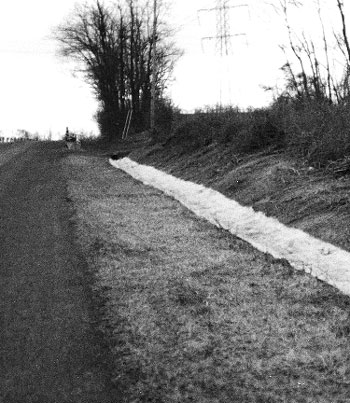
Erosion control measures such as fiber mats shown may be necessary to prevent ditch erosion.
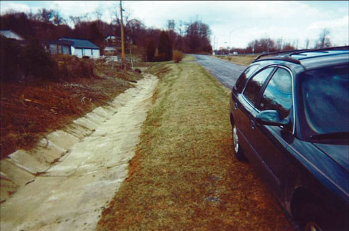
For ditches with heavy run-off, concrete lining may be necessary.
Roadside ditches, along with the other drainage features such as drop inlets, should be checked annually and after major storms to ensure they are not clogged with debris or eroded.
Roadside ditches that are not traversable by design, as a result of previous maintenance actions or because of erosion, should be redesigned to be consistent with those recommended in the current edition of the Roadside Design Guide (see discussion under section 3.2.4 Roadside Channels for preferred cross section).
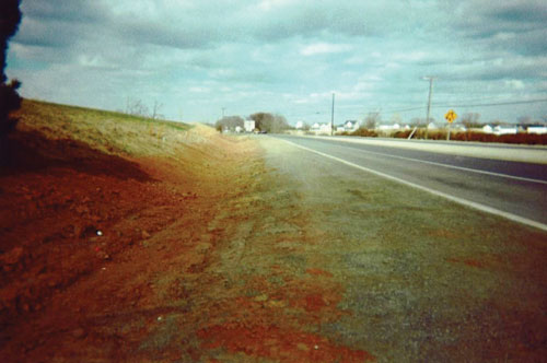
This ditch was reshaped to provide a safe recovery area for errant vehicles.
Drop inlets and catch basins in and adjacent to roadways are one of the most common drainage features especially in urban and suburban areas where curb and gutter design is used. Inlets are designed to carry surface run-off from the road and roadside away from the roadway. Inlets can be of varying design, including curb openings, grates, or a combination of these. Many local agencies use a standard design for most of their drop inlets on and adjacent to low-speed, low-volume roads. Inlets on higher level highways are often specially designed or selected to meet the conditions of greater but less frequent storms.
Drop inlets located in or adjacent to the path of motor vehicles, pedestrians and bicycles require grates that can accommodate run-off while preventing vehicles, bicycles and pedestrians from falling into the inlet. When bicycle traffic exists, grates should prevent the tires of a bicycle from slipping into and being caught in the grate. Therefore, bicycle safe grates should be used whenever bicycle traffic is expected. The photo below shows a preferred treatment for a drop inlet located on or near a bicycle travel way. With a flush bicycle-safe grate, a bicycle tire cannot get caught in the grate because of the cross pattern of supports which results in only small openings.
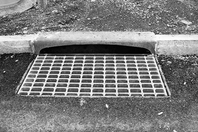
Bicycle safe grate with drop inlet.
Drop inlets should not be in the path of pedestrians. To avoid run-off across a pedestrian crosswalk it is desirable to locate the catch basin and inlet before the crosswalk as depicted on next page.
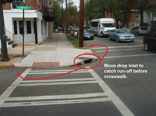
To avoid run-off across the pedestrian path, it is desirable to locate drop inlets before crosswalks.
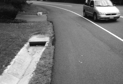
Raised roadside drop inlets, sometimes referred to as table top inlets, provide a vertical opening in their sides for large volumes of run-off and debris removal. They are usually located in low-depressed or sump areas.
Raised inlets located in areas where an errant vehicle or bicycle can drive into or over them should be no higher than 4 inches above the surrounding ground. Drop inlets that extend more than 4 inches above the surrounding ground can snag the undercarriage of a vehicle in the same way a raised headwall can, causing it to abruptly stop, go out of control, or roll over. A safer drainage treatment is to use a grated inlet that is close to the ground as shown below.

V-shaped grate in median.
Headwalls are common features on many local roadways. The headwalls are often used to support the shoulder and maintain the roadway edge, prevent the end of the pipe from being crushed or broken when overridden, collect and disperse water flows and occasionally delineate the ditch or channel. Headwalls, by their nature, are generally rigid structures capable of abruptly stopping a motor vehicle if hit. When they are located on side slopes they may be potential hazards, causing loss of control, ramping or vehicle roll over.

This culvert headwall is a roadside hazard.

In flat areas the height of the headwall should not exceed 4 inches.
In flat areas, 1V:10H or milder, fixed objects such as headwalls, should not extend more than 4 inches above the surrounding ground. Fixed objects that are higher than 4 inches can catch or snag part of a small vehicle undercarriage causing abrupt stopping, loss of control, and/or vehicle overturning.
Headwalls that are hazardous are often easy to identify by scars left on them from previous crashes. Headwalls that have been hit should be replaced with a traversable end treatment or crashworthy safety feature rather than replaced or repaired in kind. As an immediate, temporary treatment, the headwall should be delineated with a retroreflective object marker consistent with the current edition of the Manual on Uniform Traffic Control Devices.
Rigid headwall delineated with Type 3 Object Marker.
Pipe and culvert ends vary widely. Many are just extensions of the pipe beyond an embankment. These ends are used because they are inexpensive and tend to limit the erosion around the sides of the pipe, or it may be that it was simpler to just leave the last section of pipe, rather than trying to dress it. Unfortunately, many pipe and culvert ends are within the area required by a driver to recover control or stop a vehicle that has left the travel way.
When pipe or culvert ends are within this recovery area or “clear zone,” it should be designed and maintained as a traversable feature of the roadside.
Several features of a pipe or culvert end can be hazardous to motorists, bicyclists or pedestrians that leave the travel way. These features include: (1) how well or poorly the pipe or culvert end conforms to the ground, (2) the size and shape of the end opening, and (3) the orientation and location of the pipe opening.
One of the best ways to ensure that the pipe or culvert end is not hazardous is to place the end substantially beyond the clear zone. Unfortunately, cost, geography, and/or right-of-way restrictions can be factors that limit the extension of pipe and culvert ends.
In areas where potential roadside hazards already exist, such as trees that are close to the travel way, pipe and culvert ends can be extended to beyond the tree line rather than in front of it. While this action does not reduce the existing hazardous nature of the roadside, it does not create additional hazards.
End sections within the clear zone of the roadside should be designed and maintained to be traversable features. First they should conform to the ground around them. An exposed end (pipe or culvert sections sticking up above the ground) can initiate vehicle instability and cause the driver to lose control. End sections more than 4 inches above the surrounding ground can snag the undercarriage of a vehicle, causing it to stop abruptly or to vault or roll over.
To minimize the potential of vehicle snagging on the end of a pipe, it is necessary to provide a traversable end section, ensuring that either the pipe end is cut flush with the ground line, or when used, that the steel grating is sloped flush with the surface.
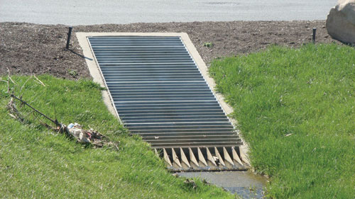
Grated inlet flush with ground over a culvert end.
A second safety consideration, important to all large pipe and culvert ends located in the clear zone, is the size or width of the opening. Pipes and culverts can trap a vehicle wheel if the opening is too large, causing it to stop abruptly or initiate overturning. Generally, openings that are larger than 30 inches are considered potential hazards; however vehicles may safely traverse over openings up to 30 inches. In crash tests of vehicles at normal highway speeds it was demonstrated that vehicle tires could cross over openings of 30 inches provided that the opening has been cut to match a traversable side slope.
This culvert has a rather large opening which could cause a vehicle that hits it to go out of control.
Large openings of pipe and culvert ends can often be made traversable for a vehicle by construction of an open pipe grate across the potential path of the vehicle. Pipe grates need to be of sufficient strength to accommodate a vehicle and should be removable or hinged to provide for maintenance. Design of the pipe grate is important to safety and varies with the size, shape, location, and orientation of the pipe.
A potential source of information on safety treatments for pipe and culvert openings is State standard drawings for highway drainage and the Roadside Design Guide. Another potential source of information are the offices of the Local Technical Assistance Program (LTAP).
Access points, such as road intersections, driveways, pedestrian and bicycle crossings are important areas where drainage features should be reviewed and, where appropriate, improvements made.
At access points the grade of the highway and the access point have to meet. Consequently, the free flow of run-off is restricted and some drainage feature is usually built to move the water away. Drainage facilities, particularly those for driveways, may have been poorly constructed by developers or property owners and may be potential hazards. Local jurisdictions may have established laws requiring access points to be free of hazards and obstacles that could affect the safety of the traveling public.
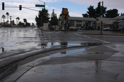
In this photo, water is ponding because the outflow ditch has silted up. Ponded water can cause drivers to leave their lane, reduce braking ability or contribute to pavement deterioration.

This grated inlet can be used to prevent water ponding at access points.
The first consideration during any installation or maintenance of drainage features is the safety of both the work crew and the motorist. Therefore, remember to follow these safety procedures:
In addition, before work begins, it is important to set up proper work zone traffic control. Appendix B provides three typical traffic control plans that may be applicable depending upon the type of work being performed-- use layout no. 1 (6H-1) when the work is beyond the shoulder area; use layout no. 2 (6H-6) when the work is being done on the shoulder, and use layout no. 3 (6H-17), if the work is a moving operation such as for cleaning out curb inlets. These are for illustrative purposes; refer to the Manual on Uniform Traffic Control Devices for more detailed guidance.
American Association of State Highway and Transportation Officials. Roadside Design Guide. 2002 Third Edition, 2006 (with updated chapter 6). Washington, D.C. (http://www.transportation.org)
Federal Highway Administration. Manual on Uniform Traffic Control Devices. 2003 Edition. (http://mutcd.fhwa.dot.gov/)
The concept of clear zone is an approach to minimize the number and severity of crashes involving vehicles running off the road or encountering slopes that may lead to instability and overturning. Simply stated, it is a traversable area that starts at the edge of the traffic lane and extends laterally a sufficient distance to allow a driver to stop or return to the road before encountering a hazard or overturning. The traversable area would be considered safe, if there were no fixed objects, unless they are breakaway, and if the roadside geometry (either the fore slope, back slope, or ditch) was flat enough that a vehicle could safely traverse the area without tipping and rolling over. Roadside safety features include breakaway sign and light posts, and traversable drainage structures. Curbs are not considered a roadside safety feature since they can be easily mounted by errant vehicles; hence, their presence does not alter how clear zone is measured.
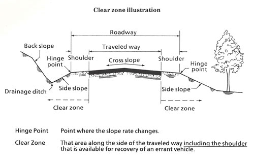
Clear zone illustration
A safe traversable slope can be either a recoverable slope or a non-recoverable slope with a clear run-out area at the bottom. A recoverable slope is a slope on which a motorist may, to a greater or lesser extent, retain or regain control of a vehicle and recover or stop. Slopes 1:4 (Vertical:Horizontal) or flatter are generally considered recoverable. A non-recoverable, traversable slope is a slope which is considered traversable but on which an errant vehicle will continue to the bottom. Embankment slopes from 1:3 and 1:4 may be considered traversable but non-recoverable if they are smooth and free of fixed objects. A clear run-out area is the flatter area at the toe of a non-recoverable slope available for safe use by an errant vehicle. Slopes steeper than 1:3 are not considered traversable and should not be found in the clear zone.
The objective of roadside safety is to provide and maintain as much clear zone as practical. The design clear zone is the minimum width to be provided on a project and is dependent upon speeds, the roadside geometry, and traffic volumes. Further details on clear zone can be found in the Roadside Design Guide.
1. Typical Traffic Control Layout for Work Beyond the Shoulder
2. Typical Traffic Control Layout for Shoulder Work with Minor Encroachment

3. Typical Traffic Control Layout for Mobile Operations on Two-Lane Road