U.S. Department of Transportation
Federal Highway Administration
1200 New Jersey Avenue, SE
Washington, DC 20590
202-366-4000
| < Previous | Table of Contents | Next > |
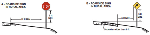
Figure 3. MUTCD Roadside Placement (MUTCD Figure 2A-2)
For a typical rural road with no shoulder, the sign should be placed on the right-hand side of the roadway, 12 feet laterally from the edge of the traveled way. In terms of vertical height, the bottom of the sign should be installed at least 5 feet above the ground elevation at the edge of pavement. Enhancing Sign Conspicuity Cost Effectively (MUTCD, Figure 2A-2).
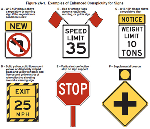
Figure 4. MUTCD Examples of Enhanced Conspicuity for Signs (MUTCD, Section 2A.15)
Minimum Sign Size: 24" x 30"
When to use
Minimum Sign Size: 36" x 36"
When to use
A Reduced Speed Limit Ahead (W3-5 or W3-5a) sign should be used to inform road users of a reduced speed zone where the speed limit is being reduced by more than 10 mph, or where engineering judgment indicates the need for advance notice to comply with the posted speed limit ahead.
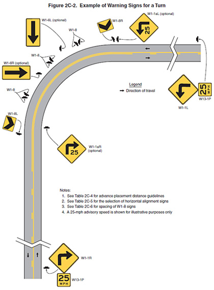
Figure 5. MUTCD Example of Warning Signs for a Turn
| Type of Horizontal Alignment Sign |
Difference Between Speed Limit and Advisory Speed | ||||
|---|---|---|---|---|---|
| 5 mph | 10 mph | 15 mph | 20 mph | 25 mph or more | |
| Turn (W1-1), Curve (W1-2), Reverse Turn (W1-3), Reverse Curve (W1-4), Winding Road (W1-5), and Combination Horizontal Alignment/Intersection (W1-10) (see Section 2C.07 to determine which sign to use) | Recommended | Required | Required | Required | Required |
| Advisory Speed Plaque (W13-1P) | Recommended | Required | Required | Required | Required |
| Chevrons (W1-8) and/or One Direction Large Arrow (W1-6) | Optional | Recommended | Required | Required | Required |
| Exit Speed (W13-2) and Ramp Speed (W13-3) on exit ramp | Optional | Optional | Recommended | Required | Required |
Note: Required means that the sign and/or plaque shall be used, recommended means that the sign and/or plaque should be used, and optional means that the sign and/or plaque may be used.
See Section 2C.06 for roadways with less than 1,000 AADT.
All square/diamond warning signs have a minimum sign size of 30" x 30".
When to use
In advance of horizontal curves on freeways, on expressways, and on roadways with more than 1,000 AADT that are functionally classified as arterials or collectors, horizontal alignment warning signs shall be used in accordance with Table 2C-5 based on the speed differential between the roadway's posted or statutory speed limit or 85th-percentile speed, whichever is higher, or the prevailing speed on the approach to the curve, and the horizontal curve's advisory speed.
Horizontal Alignment Warning signs may also be used on other roadways or on arterial and collector roadways with less than 1,000 AADT based on engineering judgment.
When to use
A Turn sign shall be used instead of a Curve sign in advance of curves that have advisory speeds of 30 mph or less.
When to use
Where there are two changes in roadway alignment in opposite directions that are separated by a tangent distance of less than 600 feet, the Reverse Turn sign should be used instead of multiple Turn signs and the Reverse Curve sign should be used instead of multiple Curve signs.
When to use
The Turn sign or the Curve sign may be combined with the Cross Road sign or the Side Road sign to create a combination Horizontal Alignment/Intersection warning sign that depicts the condition where an intersection occurs within or immediately adjacent to a turn or curve.
Elements of the combination Horizontal Alignment/Intersection warning sign related to horizontal alignment should comply with the provisions of Section 2C.07, and elements related to intersection configuration should comply with the provisions of Section 2C.46.
The symbol design should approximate the configuration of the intersecting roadway(s). No more than one Cross Road or two Side Road symbols should be displayed on any one combination Horizontal Alignment/Intersection warning sign.
Minimum Plaque Size: 18" x 18"
Roadside Placement: The sign height changes when a speed plaque is added.
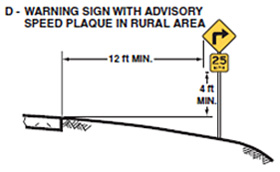
Figure 6. MUTCD Roadside Placement with Plaque
When to use
The use of the Advisory Speed plaque for horizontal curves shall be in accordance with the information shown in Table 2C-5. The Advisory Speed plaque shall also be used where an engineering study indicates a need to advise road users of the advisory speed for other roadway conditions.
If used, the Advisory Speed plaque shall carry the message XX MPH. The speed displayed shall be a multiple of 5 mph.
Except in emergencies or when the condition is temporary, an Advisory Speed plaque shall not be installed until the advisory speed has been determined by an engineering study.
The Advisory Speed plaque shall only be used to supplement a warning sign and shall not be installed as a separate sign installation.
The advisory speed shall be determined by an engineering study that follows established engineering practices. Among the established engineering practices that are appropriate for the determination of the recommended advisory speed for a horizontal curve are the following:
When to use
The Turn sign or the Curve sign may be combined with the Advisory Speed plaque to create a combination Turn/Advisory Speed sign or combination Curve/Advisory Speed sign.
The combination Horizontal Alignment/Advisory Speed sign may be used to supplement the advance Horizontal Alignment warning sign and Advisory Speed plaque based upon an engineering study.
If used, the combination Horizontal Alignment/Advisory Speed sign shall not be used alone and shall not be used as a substitute for a Horizontal Alignment warning sign and Advisory Speed plaque at the advance warning location. The combination Horizontal Alignment/Advisory Speed sign shall only be used as a supplement to the advance Horizontal Alignment warning sign.
If used, the combination Horizontal Alignment/Advisory Speed sign shall be installed at the beginning of the turn or curve.
The advisory speed displayed on the combination Horizontal Alignment/Advisory Speed sign should be based on the advisory speed for the horizontal curve and match that speed.
Minimum Sign Size: 18" x 24"
Sign Design: The Chevron Alignment sign shall be a vertical rectangle. No border shall be used on the Chevron Alignment sign.
When to use
The use of the Chevron Alignment sign to provide additional emphasis and guidance for a change in horizontal alignment shall be in accordance with the information shown in Table 2C-5.
Sign Placement
If used, Chevron Alignment signs shall be installed on the outside of a turn or curve, in line with and approximately at a right angle to approaching traffic. Chevron Alignment signs shall be installed at a minimum height of 4 feet, measured vertically from the bottom of the sign to the elevation of the near edge of the traveled way.
Spacing Around Turns/Curves
The approximate spacing of Chevron Alignment signs on the turn or curve measured from the point of curvature (PC) should be as shown in Table 2C-6. Chevron Alignment signs should be visible for a sufficient distance to provide the road user with adequate time to react to the change in alignment.
Minimum Sign Size: 48" x 24"
Sign Design: The One-Direction Large Arrow sign shall be a horizontal rectangle with an arrow pointing to the left or right.
When to use
A One-Direction Large Arrow sign may be used either as a supplement or alternative to Chevron Alignment signs in order to delineate a change in horizontal alignment (see Figure 2C-2). The use of the One-Direction Large Arrow sign shall be in accordance with the information shown in Table 2C-5.
A One-Direction Large Arrow sign may be used to supplement a Turn or Reverse Turn sign to emphasize the abrupt curvature.
Sign Placement
If used, the One-Direction Large Arrow sign shall be installed on the outside of a turn or curve in line with and at approximately a right angle to approaching traffic. The One-Direction Large Arrow sign should be visible for a sufficient distance to provide the road user with adequate time to react to the change in alignment.
Minimum Sign Sizes
Type 1: 18" x 18"
Type 2: 6" x 12"
Type 3: 12" x 36"
Sign Design: Object markers shall not have a border and shall consist of an arrangement of one or more of the following types shown in Figure 2C-13.
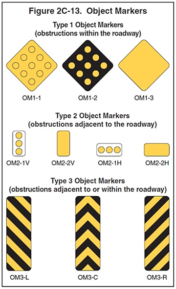
Figure 7. MUTCD Object Markers
When to use
Type 1 object markers are used to mark obstructions within the roadway.
Type 2 and 3 object markers are used to mark obstructions adjacent to the roadway.
Obstructions not actually within the roadway are sometimes so close to the edge of the road that they need a marker. These include underpass piers, bridge abutments, handrails, ends of traffic barriers, utility poles, and culvert headwalls. In other cases there might not be a physical object involved, but other roadside conditions exist, such as narrow shoulders, drop-offs, gores, small islands, and abrupt changes in the roadway alignment, that might make it undesirable for a road user to leave the roadway, and therefore would create a need for a marker.
Object Marker Placement – Type 1, 2, 3
When used for marking obstructions within the roadway or obstructions that are 8 feet or less from the shoulder or curb, the minimum mounting height, measured from the bottom of the object marker to the elevation of the near edge of the traveled way, should be 4 feet.
When used to mark obstructions more than 8 feet from the shoulder or curb, the distance from the bottom of the object marker to the ground should be at least 4 feet.
When object markers or markings are applied to an obstruction that by its nature requires a lower or higher mounting, the vertical mounting height may vary according to need.
If a Type 2 or Type 3 object marker is used to mark an obstruction adjacent to the roadway, the edge of the object marker that is closest to the road user shall be installed in line with the closest edge of the obstruction.
On roadways with center line markings, no-passing zone markings shall be used at horizontal or vertical curves where the passing sight distance is less than the minimum shown in Table 3B-1 for the 85th-percentile speed or the posted or statutory speed limit.
Figure 3B-4 details the measurements needed to determine No Passing Zones at curves.
Where the distance between successive no-passing zones is less than 400 feet, no-passing markings should connect the zones.
No Passing Zone pavement marking can be enhanced with the following signs as desired.
Minimum Sign Size: 24" x 30"
When to use
The DO NOT PASS sign may be used in addition to pavement markings to emphasize the restriction on passing. The DO NOT PASS sign may be used at the beginning of, and at intervals within, a zone through which sight distance is restricted or where other conditions make overtaking and passing inappropriate.
Minimum Sign Size: 24" x 30"
When to use
The PASS WITH CARE sign should be installed at the downstream end of a no-passing zone if a DO NOT PASS sign has been installed at the upstream end of the zone.
Minimum Sign Size: 48" x 48" x 36"
When to use
If signing is needed on the left-hand side of the roadway for additional emphasis, NO PASSING ZONE signs may be used.
When used, the NO PASSING ZONE sign shall be installed on the left-hand side of the roadway at the beginning of no-passing zones identified by pavement markings.
2009 MUTCD "Section 2A.08 Maintaining Minimum Retroreflectivity"
The MUTCD provides suggestions for methods to be used:
The retroreflectivity of an existing sign is assessed by a trained sign inspector conducting a visual inspection from a moving vehicle during nighttime conditions. Signs that are visually identified by the inspector to have retroreflectivity below the minimum levels should be replaced.
Sign retroreflectivity is measured using a retroreflectometer. Signs with retroreflectivity below the minimum levels should be replaced.
When signs are installed, the installation date is labeled or recorded so that the age of a sign is known. The age of the sign is compared to the expected sign life. The expected sign life is based on the experience of sign retroreflectivity degradation in a geographic area compared to the minimum levels. Signs older than the expected life should be replaced.
All signs in an area/corridor, or of a given type, should be replaced at specified intervals. This eliminates the need to assess retroreflectivity or track the life of individual signs. The replacement interval is based on the expected sign life, compared to the minimum levels, for the shortest-life material used on the affected signs.
Replacement of signs in the field is based on the performance of a sample of control signs. The control signs might be a small sample located in a maintenance yard or a sample of signs in the field. The control signs are monitored to determine the end of retroreflective life for the associated signs. All field signs represented by the control sample should be replaced before the retroreflectivity levels of the control sample reach the minimum levels.
Other methods developed based on engineering studies can be used.
Additional guidance on retroreflectivity requirements for various signs is provided in Table 2A-3.
| Sign Color | Sheeting Type (ASTM D4956-04) | Additional Criteria | |||
|---|---|---|---|---|---|
| Beaded Sheeting | Prismatic Sheeting | ||||
| I | II | III | III, IV, VI, VII, VIII, IX, X | ||
| White on Green | W*; G ≥ 7 | W*; G ≥ 15 | W*; G ≥ 25 | W ≥ 250; G ≥ 25 | Overhead |
| W*; G ≥ 7 | W ≥ 120; G ≥ 15 | Ground-mounted | |||
| Black on Yellow or Black on Orange |
Y*; O* | Y ≥ 50; O ≥ 50 | (2) | ||
| Y*; O* | Y ≥ 75; O ≥ 75 | (3) | |||
| White on Red | W ≥ 35; R ≥ 7 | (4) | |||
| Black on White | W ≥ 50 | — | |||
| 1 The minimum maintained retroreflectivity levels shown in this table are in units of cd/lx/m2 measured at an observation angle of 0.2 ° and an entrance angle of -4.0 °. 2 For text and fine symbol signs measuring at least 1200 mm (48 inches) and for all sizes of bold symbol signs 3 For text and fine symbol signs measuring less than 1200 mm (48 inches) 4 Minimum Sign Contrast Ratio ≥ 3:1 (white retroreflectivity ÷ red retroreflectivity) * This sheeting type should not be used for this color for this application. |
|||||
| Bold Symbol Signs | ||
|---|---|---|
|
|
|
| Fine Symbol Signs – Symbol signs not listed as Bold Symbol Signs. |
|---|
| Special Cases |
|
| < Previous | Table of Contents | Next > |

