U.S. Department of Transportation
Federal Highway Administration
1200 New Jersey Avenue, SE
Washington, DC 20590
202-366-4000
| < Previous | Table of Contents | Next > |
Figure 1 shows the safety process from the Toolkit. To study safety conditions at the curve and identify if countermeasures should be implemented, and what type of countermeasures are appropriate to implement, the manager of the Department of Public Works will need to apply:
Each of the analysis steps is described below. Steps 2 and 3 are not necessary because the location of interest has been already pinpointed by the public.
The first step in conducting the analysis for this scenario is to compile and evaluate the available data. The data available influences the type of analyses that can be conducted. Typically, the information available can be divided into quantitative information and anecdotal information.
Table 1 summarizes the quantitative information that might be collected for this situation, and shows the data types that this scenario assumed are available. More information about sources for and how to work with each data type follows in this section.
There also are often regional and state organizations available to provide guidance or data for conducting safety analyses. It is useful to get to know staff in the safety group at your state’s DOT or planners or engineers at your Council of Governments (COG) or Metropolitan Planning Organization (MPO), as they also could assist you in conducting safety analyses.
Typically, there are statewide documents that may be available to support a site-specific traffic safety study. For example, the state Strategic Highway Safety Plan (SHSP) may contain information about crash types that are of particular concern in the state and/or countermeasures known to be applicable in the state. Some states have plans focusing on specific safety issues such as intersections or run-off-road crashes. These documents also can be resources for understanding factors contributing to crashes, possible treatments, and funding sources to address the safety concern.
In this scenario, the anecdotal information is gathered from conversations with the community officials, community residents, and road maintenance workers that travel through the curve on a regular basis. The information gathered indicates there is a perception that the curve is too sharp, and that drivers are going too fast leading into the curve. For instance, residents described “near misses” they have experienced and helping to tow cars out of the adjacent ditch. This type of anecdotal information can be a good source of information and clues as to what should be studied at the site.
Is Anecdotal Data Valuable?
Many times anecdotal data may provide information that is not reflected in the site crash history. This can include information relating to minor crashes that are below a reporting threshold, near misses, and other vehicle conflicts that do not result in a reportable crash. This information can be valuable in providing clues on where to start a data-driven investigation. The challenge with anecdotal data is sorting out what issues are the perception of safety issues versus actual addressable safety issues.
The crash data on printed crash forms can be acquired from the local police or sheriff department, or from the state department managing the crash data, often the DOT.
Understanding Crash Location
There are many ways to specify and record crash location on the crash record or in the crash database.
One common method is “road on and milepoint range.” In this method the crash location is specified by recording the “road on” which the crash occurred and a “milepoint range” or distance from a beginning point. For example a crash could occur on Main Street, 0.20 miles from First Street.
Recently, many crashes are geocoded. When a crash location is geocoded, it is assigned a pair of geographic coordinates such as longitude and latitude. Crashes can then be mapped electronically using these coordinates.
Local and Tribal police agencies typically only hold the crash records that their officers have created, so their records may be missing crashes if there are other police agencies that have jurisdiction in the area, or if the crash is not reported at all. Most states only require crashes to be reported if the dollar value of damages exceeds a minimum, or an injury occurs. Usually, the more severe the crash, the more likely the crash is reported to the police.
The state DOT, state police agency, or department of public safety in most states compile and hold all crash records from all police agencies in the state. Often, one of these organizations will publish a yearly summary of crashes in a report or database. State databases may not include crashes in Tribal areas.
What to look for on a Crash Report
Information on a crash report that can provide clues to the factors that led to the crash include:
The officer’s diagram and written description of the crash can also provide invaluable information that can assist in understanding what occurred at the crash site. Information to be gleaned from these two sources include the officer’s opinion on what caused the crash and details on the vehicles’ exact path when the crash occurred.
When requesting crash data, it is best to collect as much data as possible. At a minimum, the practitioner should gather at least three years of crash data for a specific site. Many states have automated this request process and have on-line data request forms, or have a log-in procedure access on-line crash databases.
In this scenario, the crash data is acquired from the agency police department and is provided in completed paper crash forms. All crash forms use abbreviations and notations that can seem cryptic or can be misleading without a key to the form. To address this, almost every state-level crash form also has an accompanying document that details what the form abbreviations mean and give criteria for determining how to code certain data elements. Figures 3 (Michigan Crash Report Form) and 4 (Key for Crash Report Form) on pages 8 and 9, respectively, illustrate some key fields and their meanings for assessing crash data.
Example Email Request for Crash Data from a State DOT
Hi Ms. Smith,
My community is studying safety conditions on River Road between Third Avenue and Fir Street. In order to complete my analysis, I will need to study the available crash data for this segment. Please provide the most recent three calendar years of data you have for crashes in this segment of River Road.
Please provide the information by individual crash record so that we can summarize crashes by type, severity, time of day, day of week, and environmental conditions (for example, weather, roadway dry or wet). If possible, please provide the data in a spreadsheet so that we can more easily summarize the information. If this is not possible, that is fine too.
If the data contains codes to specify information such as crash type, severity, or impairment, please provide me a copy of the document defining the codes. If this is available on-line, please just provide the link to the site.
Please confirm that you have received this request and let me know when you will be able to provide the information. If you have any questions, please call me to discuss. My contact information is below.
Thanks in advance,
Clark White
Figure 3. Example Crash Form from Michigan (UD-10 Form)
Source: Michigan Department of Transportation, UD-10 Traffic Crash Report Manual.
Figure 4. Example Key for Crash Form from Michigan (UD-10 Form)
Source: Michigan Department of Transportation, UD-10 Traffic Crash Report Manual.
Quantitative traffic volume data may be available through other work conducted at or near a site. There may be an annual traffic counting program, or traffic counts may have been conducted as part of a construction project. If not available within the agency, the state DOT, Council of Governments (COG), Local Technical Assistance Program (LTAP), or Tribal Technical Assistance Program (TTAP) may have the data or can provide support in acquiring the data. If no traffic volume data is available, anecdotal perceptions of traffic volume as “low,” “average,” or “high” relative to comparable roads in the community can be acquired from local stakeholders familiar with the site. This information can be useful to get a perspective on the order of magnitude of exposure to the safety concern.
In this example, the agency does not have access to roadway traffic volume data. Even though exact traffic counts are not available, staff indicate that the traffic volume on River Road is “about the same” when compared to other roads in the county. At a minimum, this qualitative assessment of the traffic volume should be recorded in the project documentation and can provide some basis for comparison of crash histories between this segment and others in the county.
To the greatest extent possible, a site visit should always be part of the safety analysis process to get a feel for site conditions and get an understanding of existing and potential safety issues.
Field Visits are Important to Do
It is important for the practitioner to make a field visit. Viewing the site in-person allows the practitioner to observe traffic and other features that data or photos alone cannot convey.
The type of data collected during a site visit should include number of lanes, lane width, shoulder width and type, sight distance where it appears limited, posted speed limit, and other signage. Videotape or photographs are also very helpful in documenting conditions.
A field visit after dark is also very important to evaluate the signing and pavement marking. The Road Safety Audit (RSA) Guidebook and Highway Safety Manuals have prompt lists that can assist in field visit data collection. See the Toolkit for more information on these resources.
The type of roadway characteristics data to collect during a site visit includes:
Possible sources for the roadway characteristics data are roadway design or maintenance staff, state DOT roadway databases or as-built drawings, on-line mapping tools such as Google Street View™ mapping service, and/or an on-site field visit.
Roadway characteristics are used in the scenario analysis to support the diagnosis and potential countermeasure selection. Roadway characteristics are best collected by visiting the site, taking photos, and recording the physical site characteristic. The FHWA document, FHWA Road Safety Audit Guidelines, provides many resources for formal or informal site inspections. The document provides prompt lists, which can act as a field visit outline. It may be useful to visit the site after dark. As the safety analysis proceeds, it may be useful to visit the site again to help with the diagnosis of crash conditions.
Field Evidence Demonstrating a Potential Safety Issue
Some very subtle signs of a safety problem can be uncovered during a site visit. These include skid marks on the road or shoulder, scarred or damaged trees, debris from damaged vehicles, or damaged signs.
To the greatest extent possible, site data information should be hand drawn on a site conditions map (see Figure 5).
Google Maps™ mapping service or Bing® maps, if available, can supplement a site visit. Before the site visit, it can be useful to get initial community and local perceptions of the site; and after the site visit, these perceptions can be useful reminders of the site’s conditions.
Figure 5. Example Site Conditions Map
There may be other agency-specific or statewide documents that contain information useful for the analysis.
The safety analysis in this scenario will be based on the site field investigation information, a summary of the crash data, and the qualitative assessment of traffic volume.
With the data compiled and the field visit complete, the next steps in a site-specific safety analysis are to analyze the crash data, traffic volume data, and roadway characteristics data to begin to understand contributing factors to the safety concerns at the site. This is called “diagnosis.” As an outcome of the diagnosis, it is possible to identify potential countermeasures for implementation at the site.
Why analyze crash data?
The purpose of analyzing crash data is to determine factors that may be common across a number of crashes. These patterns can sometimes be evident by summarizing data by factors that contribute to the safety issue. This can include environmental factors, such as wet/dry roadway, or day/night driving; and driver factors, such as distraction, age, or use of alcohol/drugs.
The crash data collected in Step 2 should be summarized in tabular form and, if possible, crash location also should be mapped. Crashes can be mapped at a site manually on a paper map, or by using free mapping tools available on-line.
This scenario summarizes crash counts by year, type, severity, and other environmental factors. Table 2 shows a summary of crash count by year and severity. This table shows 22 of the 37 crashes were property damage-only crash, and there was one fatal crash in 2007 and another in 2010. A summary like Table 2 can show crash frequency trends on an annual basis.
Crash Severity KABCO System
Crash Severity: The KABCO Scale is used to classify crashes by injury severity. The letters represent injury levels as follows:
Table 3 shows the site crash data summarized by year and crash type. This table shows the most common crash type is run-off-road crashes, and most of these crashes occurred in 2009. Note that in some situations run-off-road crashes also can be fixed-object crashes if an object is hit after the road departure. The crash records should be carefully evaluated to confirm that double counting is not occurring.
| Year | Run Off The Road | Fixed Object | Head-On | Other |
|---|---|---|---|---|
| 2011 | 4 | 2 | 0 | 1 |
| 2010 | 5 | 2 | 1 | 1 |
| 2009 | 7 | 2 | 0 | 1 |
| 2008 | 0 | 3 | 0 | 1 |
| 2007 | 3 | 3 | 1 | 0 |
| Total | 19 | 12 | 2 | 4 |
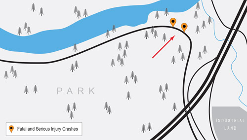
Figure 6 provides a graphical display of the location of the fatal and serious injury crashes. Alternatively, Google Map Maker™ service in Google Earth™ mapping service can be used to create an electronic map of site conditions. Specifically, the Add a Place pushpin function can be used.
Figure 6. Incapacitating Injury Crashes
After crash summaries have been developed and studied in the office, a second field visit can be useful to reconsider the site with the site’s crash history in mind.
For site inspection to be productive, the person or people conducting the site visit will benefit from understanding how field conditions relate to safety issues. This understanding can be developed through knowledge of geometric design standards, the proper use of traffic control devices, and other safety-related topics. The resources presented after each step in the Toolkit provide a wealth of information for developing this knowledge base.
The field review also could be conducted as a formal Road Safety Audit (RSA). If an RSA is being conducted, agencies should develop a multidisciplinary team of experts to participate in the RSA. FHWA Road Safety Audit Guidelines provide guidance on conducting RSAs. Additionally, if needed, staff can seek out technical assistance/expertise from the state DOT, LTAP/TTAP, county engineer, or qualified consultant.
As an outcome of the site visit conducted for this project, the practitioner learned the following, as shown in Table 4. This table shows a field review evaluation prompt list and the information recorded during the field visit. As described in the resources section of Step 4 of the Toolkit, prompt lists like this one can be found in many different resources.
To identify the contributing factors, feature, or crash type to investigate, crash data is compared and contrasted to the results of the field visit and summarized.
In this scenario, the site visit and crash data evaluation show:
Based on the existing crash data and field investigation, the site’s run-off-road crashes included the two fatal crashes and were the most frequent crash type. The investigation also showed that existing roadway features may not sufficiently inform drivers of upcoming conditions; therefore, safety treatments should focus on the roadway departure crashes.
The FHWA Office of Safety web site has a web page focused on roadway departure crashes. This web site provides information about how common roadway departure crashes, particularly on horizontal curves, and provides information about countermeasures to address these types of crashes.
It is often useful at this stage of the analysis to prepare an existing conditions memorandum/write-up to document the evaluation and current conclusions. A possible outline for documentation of the work through this stage of the analysis is shown below.
Introduction
Data Collection and Evaluation
Diagnosis Results
The most common and readily available resources for identifying possible treatments (countermeasures) to address a particular crash type are the web-based CMF Clearinghouse, Part D of the Highway Safety Manual, the National Cooperative Highway Research Program (NCHRP) 500 reports, and the FHWA Office of Safety Proven Countermeasures web page. Another useful resource is the FHWA document Low-Cost Countermeasures for Horizontal Curve Safety. These and other resources are presented in Step 4 of the Toolkit.
Looking for patterns in crash data
Studying the crash type, severity, and environmental conditions will provide insights for identifying potential crash contributing factors and potential treatments. For example, if a site had very high nighttime crash frequency, then lighting might be a treatment to reduce crash frequency. Or if there were many crashes on Friday nights after high school football games, education about speeding and distracted driving or speed enforcement might be a more useful countermeasure. It is important to remember that infrastructure will not always address site issues.
The Crash Modification Factors (CMF) Clearinghouse serves as a central on-line database of countermeasures and their associated CMFs. The CMF Clearinghouse defines a crash modification factor as “a multiplicative factor used to compute the expected number of crashes after implementing a given countermeasure at a specific site.” Users are able to query the Clearinghouse database to identify treatments and the associated CMF. For each CMF, the database provides users with published information, such as how it was developed, the research quality behind the CMF, and a link to the publication from which the CMF was extracted. Based on this information, users are able to determine the most applicable CMF for their condition.
The NCHRP 500 consists of multiple reports, each report addresses a specific type of highway crash or contributing factor. Volume 06, A Guide for Addressing Run-Off-Road Collisions is applicable to this situation. This document provides information about typical conditions related to run-off-road crashes, strategies for addressing the crashes, and guidance for implementing solutions. In this document, the countermeasures are reported as “proven,” “tried,” and “experimental.” Proven countermeasures are the preferred countermeasures for implementation. Note that since this series of documents was originally published, new research may have been conducted that may have reclassified some countermeasures from “experimental” to “tried,” or from “tried” to “proven.”
What to do if the potential safety issue is not obvious?
Sometimes, there is not an obvious pattern in the data leading to a potential safety issue or treatment. This can affect proper diagnosis of the safety issue. Options for dealing with this difficult safety situation include the following:
In the case of identifying countermeasures for a specific crash type at a specific location, it is worthwhile to return to the FHWA Office of Safety web site and review the web page dedicated to “proven countermeasures”. This web page provides information about countermeasures known to address specific crash types. The web page contains information related to rumble strips and stripes, and enhanced delineation, and friction for horizontal curves and the safety edge. Each of these countermeasures addresses run-off-road crashes and may be applicable to the study site.
This scenario’s site diagnosis determined that countermeasures, which may reduce run-off-road crashes, are appropriate at the study site. Based on this conclusion, the scenario can identify countermeasures that address run-off-road crashes using the aforementioned resources.
Countermeasures and Treatments
The terms “countermeasures” and “treatments” are often used interchangeably to mean a strategy or action implemented to reduce the frequency or severity of crashes at a site.
To find countermeasures in the CMF Clearinghouse database, users query the Clearinghouse for CMFs related to a particular treatment or crash type (in this case, run-off-road crashes). There are search filters provided to help narrow the results. The search filters are by star quality or the research quality behind the CMF, crash type, crash severity, roadway type, area type, intersection type, intersection geometry, traffic control, and whether the countermeasure is in the AASHTO Highway Safety Manual (HSM). For this scenario, a search for a treatment related to run-off-road crashes with filters for all star ratings, run-off road crash types, any crash severity, and in rural area shows treatments for run-off-road crashes in the following categories of potential treatments (countermeasures):
Each of these categories contains treatments for reducing run-off-road crashes and these treatments CMF developed from research. For example, the countermeasures contained in the Signs category are:
The information about each of these treatments in the above categories needs to be studied to determine the potential application of the treatment to this scenario. For example in Figure 7, the treatment related to install chevrons in curves provides five different four-star-rated CMFs.
Figure 7. CMF Clearinghouse Countermeasure Example Install Chevrons
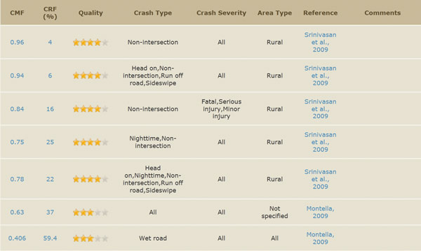
Source:Crash Modification Factors Clearinghouse.
To select a countermeasure, the possible treatments in each of the categories would be examined to identify how applicable the treatment is for the situation at hand. The Clearinghouse provides an option to export the query for review and evaluation in Microsoft Excel. In all likelihood, there will not be a perfect match between the countermeasures in the Clearinghouse and the specific site under investigation. However, the best available treatment can be selected for application based on good judgment and familiarity with the site conditions. Things to consider as part of CMF selection process include specific roadway type, urban, suburban rural environment, specific volume range, or addressing a particular crash type or severity. If a CMF’s situation is not similar to the site at hand, the same safety effectiveness cannot be expected. Remember, the lower the CMF the greater the potential reduction in crashes. However, there may be tradeoffs or barriers to implementing the CMF with the lowest value. This is acceptable and part of the judgment process of selecting countermeasures.
If the CMF Clearinghouse does not provide an option for a treatment for the particular scenario, the FHWA Office of Safety web site and the NCHRP 500 report may also provide insight, or the state DOT might have a list of treatments and CMF values approved for use in the state.
Following review of the Clearinghouse and the FHWA Office of Safety web site, the treatments in Table 5 were selected as optional treatments applicable at the site under investigation. Figures 8 and 9 show example images of these optional treatments.
Figure 8. Potential Treatment Enhanced Signage
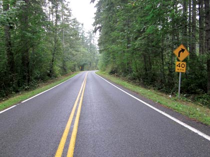
Source: Scott Davis, Thurston County, Washington.
Figure 9. Potential Treatment Install Edgeline Rumble Strips
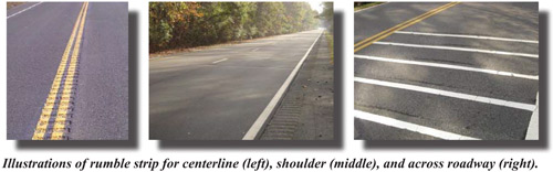
Source: FHWA.
The process for prioritizing and selecting countermeasures for implementation can range from a quantitative benefit/cost analysis to a qualitative rating process using high, medium, and low (or good, fair, poor ratings); or a hybrid of both. The purpose of the countermeasure evaluation and prioritization step is to review the potential countermeasures and select the most feasible countermeasure for the site under investigation. The types of criteria that may influence the feasibility of a particular countermeasure in a particular situation include:
The criteria for selecting a countermeasure in this scenario are environmental impacts, safety effectiveness, construction costs, maintenance costs, right-of-way impacts, and timeline to implementation. Different criteria will be important in different situations and communities, and the Toolkit presents the array of criteria that could be considered.
The results of the qualitative rating process are shown in Table 6. The impacts of each optional countermeasure were compared to the selected evaluation criteria and given a high, medium, or low rating. For example, enhanced signage received a “low” rating for environmental impacts because staff are aware that signs could easily be placed with limited, if any, impact to vegetation, hillside slopes, or the adjacent creek. In contrast, increasing lateral clearance received a “high” rating in the environmental impacts category because trees would need to be removed to increase roadside clear zones. The evaluation team also noted the potential negative impacts of edgeline rumble strips on the bicyclists in the area.
As shown above, the impacts of enhanced signage are lowest and the CMF is most specific to the study site; therefore, this countermeasure is selected for implementation.
At the end of this stage, it is appropriate to revisit the summary of existing conditions documented at the end of the previous step, and expand the memorandum/write-up to include an explanation of the analysis, countermeasure prioritization, and recommended treatments. This information also could be presented to agency leadership for review, input, and approval, if necessary. At this stage, the project documentation outline could be:
Introduction
Data Collection and Evaluation
Diagnosis Results
Countermeasure Prioritization
Recommendations
Obtaining the necessary human and financial resources to implement any safety project or program is a major consideration. Harnessing local funding sources and staff resources is often the quickest way to implement projects. For example, maintenance or public works staff can implement low-cost projects such as maintenance or replacement of signs, maintenance of striping, and/or vegetation control as part of their regular duties.
Seek Technical Assistance if Needed
If in-house expertise to work with the MUTCD or other guidelines appropriate for the project is not available, technical assistance is always available through the LTAP/TTAP, regional or metropolitan planning organization, or the state DOT.
In addition to local funds, the Local Technical Assistance Program (LTAP) web site describes the various types of local agency support provided by state DOTs – a useful first stop for identifying the resources available by state.
Implementing enhanced signage is a relatively low-cost countermeasure. In some cases, enhanced signage could be implemented as part of ongoing maintenance activities. The Toolkit provides additional information about funding opportunities.
Consider Applying Results from One Study to Other Comparable Locations
Based on the results of this assessment, a systemic analysis could be conducted to identify locations with similar configurations and safety risk. As in this case, enhanced signage could be considered for implementation at selected locations throughout the community.
The Manual on Uniform Traffic Control Devices (MUTCD) should be consulted for guidance and requirements related to sign size, placement, and retroreflectivity. Figure 10 below is an incomplete excerpt (notes and advisory speed signage information are not included in the figure in order to focus on curve delineation) of Figure 2C2 from the 2009 MUTCD, illustrating the recommended curve delineation sign layout for a horizontal curve. The MUTCD provides detailed information used to customize this layout to the specifics of the curve.
Figure 10. MUTCD Excerpt on Chevron Sign Spacing
Source: FHWA.
For example, Table 7 from the MUTCD illustrates the spacing of chevron signs based on the radius of the curve being delineated. In this scenario, the curve has a radius of 228 feet which results in a chevron sign (W1 8L) spacing of 80 feet along the outside of the curve.
Source: MUTCD.
Note: The relationship between the curve radius and the advisory speed shown in this table should not be used to determine the advisory speed.
Alternatively, if the curve radius is not known, it can be calculated using the information in Figure 11.
Figure 11. Curve Radius Calculation
Finally, if other aspects of the project have been documented, it would be useful to add the results of this step to the project documentation as well. At this stage, the project documentation outline could be:
Introduction
Data Collection and Evaluation
Diagnosis Results
Countermeasure Prioritization
Recommendations
Final Comments
If possible, it is useful to conduct a quantitative analysis to see if the crash frequency or severity has changed after implementing the treatments. Two to three years after implementing the treatment, agency staff should routinely conduct additional analyses to evaluate treatment effectiveness.
In this scenario, assuming traffic volume does not change dramatically, crash records for the three-year period after implementing the treatment should be collected, summarized, and compared to the crash data summarized for this analysis. Table 8 shows an example of a tabular comparison of the before-and-after period crash data. As shown in the table, the run-off-road crashes decreased after implementing enhanced signage. However, because of statistical issues associated with crash data (explained in the Toolkit) it should not be concluded that there was an 88 percent reduction in run-off-road crashes ((19-2)/19 = 89.5%). It can be concluded that run-off-road departure crashes have decreased, but this analysis is not statistically rigorous enough to quantify the change in crash frequency.
Note that the crash frequency for fixed-object and other crashes increased in the after-period. It is not possible to know if this is due to the treatment installed or a random fluctuation in crashes.
| Crash Type | Before (2009-2011) | After (2013-2015) |
|---|---|---|
| Run Off The Road | 19 | 2 |
| Fixed Object | 12 | 8 |
| Head-on | 2 | 2 |
| Other | 4 | 6 |
| Total | 37 | 18 |
It also is important to note that if traffic volume changes substantially after implementing the treatment at the site, this type of simple before-and-after crash analysis will be less valid because the change in traffic volume may be influencing the change in crash frequency or severity. For example, a significant decrease in crash frequency recorded in Table 8 may be due partially to the decrease in study area traffic volume.
Documenting the results of the effectiveness analysis in a memo, or for presentation to governing board would be useful. This could demonstrate the value of the project in the specific jurisdiction and serve as a resource if similar projects are considered in the future.
You may need Adobe® Reader® to view the PDFs on this page
| < Previous | Table of Contents | Next > |

