U.S. Department of Transportation
Federal Highway Administration
1200 New Jersey Avenue, SE
Washington, DC 20590
202-366-4000
This section of the Desk Reference illustrates treatments for 16 different design elements in order to accommodate the needs and enhance the performance of road users with age-related diminished capabilities as they approach and negotiate intersections. Following these proven practices, eight additional promising practices are addressed.
Proven Practices
Promising Practices
The HSM (page 10-32) defines skew angle as: intersection skew angle (in degrees); the absolute value of the difference between 90 degrees and the actual intersection angle.
In the design of new facilities or redesign of existing facilities where right-of-way is not restricted, all intersecting roadways should meet at a 90-degree angle (as indicated in Figure 3).
In the design of new facilities or redesign of existing facilities where right-of-way is restricted, intersecting roadways should meet at an angle of not less than 75 degrees (as indicated in Figure 4).
At skewed signalized intersections where the approach leg to the left intersects the driver's approach leg at an angle of less than 75 degrees, prohibit right turn on red (RTOR) (see Figure 5).
The rationale and supporting evidence for these treatments begins on page 96 of the Handbook.
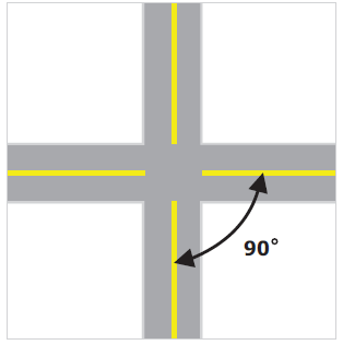
Figure 3. Example 90° angle of intersection
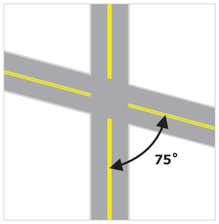
Figure 4. Example 75° angle of intersection
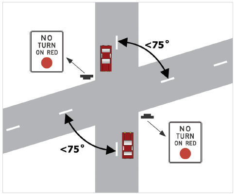
Figure 5. Skewed signalized intersection with prohibition of right turn on red
Wherever practical, a minimum receiving throat width of 16 ft is recommended. The total width may include a travel lane of 11 to 12 ft and a paved shoulder or bicycle lane of 4 to 5 ft as shown in Figure 6.
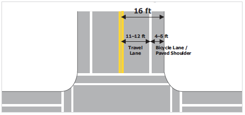
Figure 6. Recommended receiving lane width
The rationale and supporting evidence for this treatment begins on page 99 of the Handbook.
Raised channelization with sloping curbs (see Figure 7) is recommended over channelization accomplished through the use of pavement markings alone (flush) for left- and right-turn lane treatments at intersections on all roadways with operating speeds of less than 45 mph.
Where raised channelization is implemented at intersections (see Figure 7) the median and island curb sides and curb horizontal surfaces should be treated with retroreflectorized markings, such as edge lines, painted curbs, or raised pavement markers, and be maintained at a minimum luminance contrast level* as follows:
Contrast should be calculated according to this formula:

* Luminance is the amount of light reflected from an object. This is different from retroreflectivity, which is a property of a material. While increasing retroreflectivity generally results in higher luminance, (often described as brightness)—especially at night—this may vary greatly for the same object or marking depending upon such factors as the location and intensity of the source of illumination, and the angle at which a driver views it.
If right-turn channelization is present at an intersection, an acceleration lane providing for the acceleration characteristics of passenger cars as delineated in AASHTO (2011) specifications is recommended for operating speeds of 45 mph or greater.
The use of sloping curbs rather than vertical curbs (see Figure 7) for channelization is recommended, except where the curbs surround a pedestrian refuge area or are being used for access control. Vertical curbs should also not be used for channelization on high-speed (i.e., 45 mph or greater) roadways.
If right-turn channelization is present and pedestrian traffic may be expected based on surrounding land use, it is recommended that an adjacent pedestrian refuge island, conforming to MUTCD (2009) and AASHTO (2011) specifications, be provided.
To reduce unexpected midblock conflicts with opposing vehicles, the use of channelized left-turn lanes in combination with continuous raised-curb medians is recommended instead of center, two-way, left-turn lanes (TWLTL) for new construction or reconstruction where average daily traffic volumes exceed 20,000 vehicles per day, or for remediation where there is a demonstrated crash problem, or wherever a need is demonstrated through engineering study.
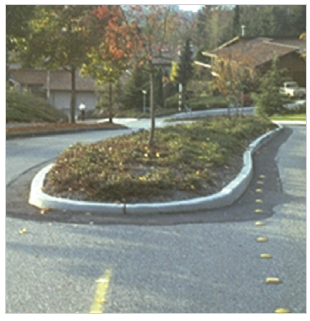
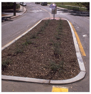
Figure 7. Vertical Curb (top), Sloping Curb (bottom)
The rationale and supporting evidence for these treatments begins on page 102 of the Handbook.
It is recommended that a gap of no less than 8.0 s, plus 0.5 s for each additional lane crossed, be used in intersection sight distance (ISD) calculations to accommodate the slower decision-making and maneuver times of aging drivers for the following cases:
Note: Cases refer to the intersection control cases defined in the AASHTO Green Book (2011).
The rationale and supporting evidence for these treatments begins on page 107 of the Handbook.
Left-turn lanes should be positively offset (as shown in Figure 8) at least 4 ft to the left of the opposing left-turn lane to achieve the desired sight distance for the left-turning driver. This will provide a margin of safety for aging drivers who, as a group, do not position themselves to the far left within the lane and within the intersection before initiating a left turn.
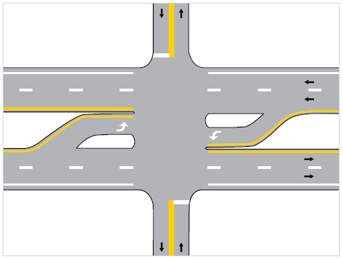
Figure 8. Left-turn lanes with positive offset
At intersections where engineering judgment indicates a high probability of heavy trucks as the opposing left-turning vehicles, the positive offset is recommended to be 5.5 ft to achieve the desired sight distance.
At locations where the full offset distances cannot be obtained, it is recommended that the minimum offset distances shown in Table 6 be provided to achieve minimum required sight distances according to design speed. It is recommended that the "Opposing Truck" values be used where the opposing left-turn traffic includes a moderate to heavy volume of large trucks.
| Design Speed (mph) | Minimum Offset (ft) | |
|---|---|---|
| Opposing Car | Opposing Truck | |
| ≤30 | 0.8 | 3.0 |
| 35 | 1.4 | 3.5 |
| 40 | 1.8 | 3.8 |
| 45 | 2.1 | 4.1 |
| 50 | 2.4 | 4.2 |
| 55 | 2.6 | 4.4 |
| 60 | 2.7 | 4.5 |
| 65 | 2.8 | 4.6 |
| 70 | 2.9 | 4.7 |
1 ft = 0.305 m
At intersections where the left-turn lane treatment results in channelized offset left-turn lanes (e.g., a parallel or tapered left-turn lane between two medians), the following countermeasures (see Figure 9) are recommended to reduce the potential for wrong-way maneuvers by drivers turning left from a stop-controlled intersecting minor roadway:
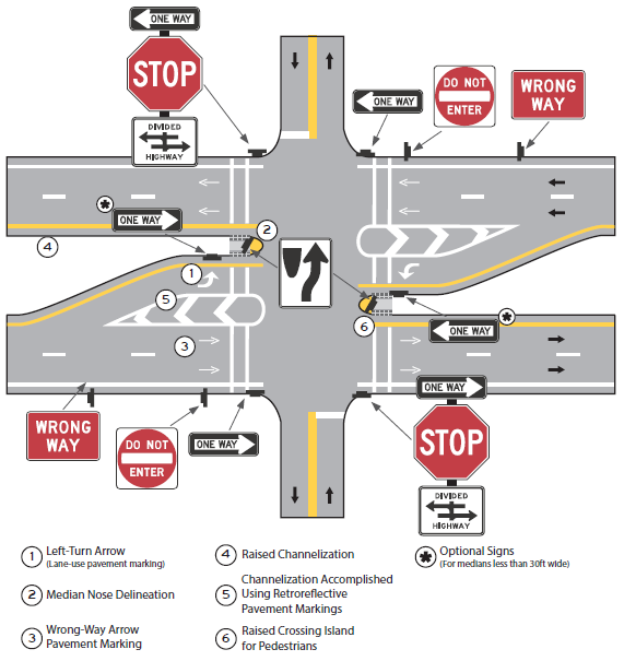
Figure 9. Recommended signs and markings for intersections with channelized offset left-turn lanes
At intersections where there are high pedestrian volumes, and the offset left-turn treatment results in a crossing width that would require a pedestrian walking at 3.0 ft/s to cross in two stages, the following is recommended to create a pedestrian crossing island (or refuge area), as shown in Figure 10:
The rationale and supporting evidence for these treatments begins on page 122 of the Handbook.
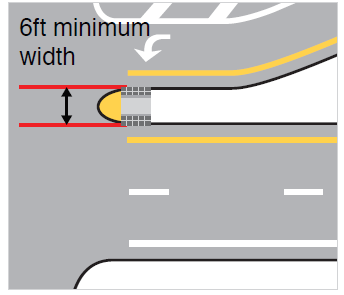
Figure 10. Pedestrian Crossing Island (or Refuge Area)
A minimum in-service luminance contrast level between the marked edge of the roadway and the road surface should be maintained as follows:
Contrast should be calculated according to the formula shown for Treatment 3: Channelization on page 10.
Curbs at intersections (including median islands and other raised channelization) should be delineated on their vertical face and at least a portion of the top surface, in addition to the provision of a marked edge line on the road surface (see Figure 11).
The use of a Keep Right (R4-7 Series) or a Double Arrow (W12-1) sign with the addition of a low-mounted Type 1 Object Marker (OM1-1) near the median and channelizing island noses, respectively, could also be helpful to aging road users. These signs are optional and can be used if they are warranted. Since markings primarily supplement signing, this treatment should be placed in addition to the signing available for these locations.
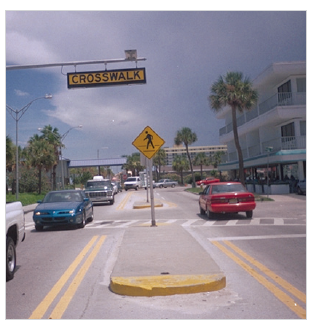
Figure 11. Raised median island with yellow marking on the vertical face and top surface
The rationale and supporting evidence for these treatments begins on page 129 of the Handbook.
Where roadways intersect at 90 degrees and are joined with a simple radius curve, a corner curb radius in the range of 25 ft to 30 ft is recommended to: (a) facilitate vehicle turning movements, (b) moderate the speed of turning vehicles, and (c) avoid unnecessary lengthening of pedestrian crossing distances (see Simple Curve in Figure 12).
When it is necessary to accommodate turning movements by large trucks, the use of offsets, tapers, and compound curves is recommended in place of larger simple radii (e.g., 75 ft or more) to minimize pedestrian crossing distances (see Figure 12).
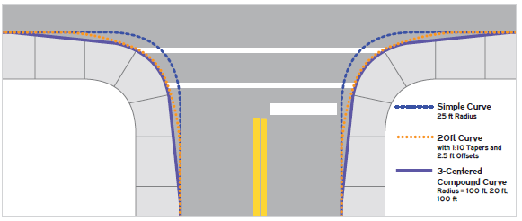
Figure 12. Comparison of curb radii
The rationale and supporting evidence for these treatments begins on page 132 of the Handbook.
The use of protected-only left-turn operations is recommended for all left-turning movements, whenever appropriate. In particular, protected-only left-turn phasing should be considered where minimum intersection sight distance requirements are not achieved through the use of offset left-turn lanes (see Design Element 5) or other geometric design features, or where a pattern of permissive left-turn crashes occurs.
If circular green is used as the permissive indication of a protected/permissive left-turn, consistent use of the MUTCD R10-12 sign, (LEFT TURN YIELD ON GREEN ![]() ) is recommended, with overhead placement preferred at the intersection adjacent to the left-turn signal face (see Figure 13).
) is recommended, with overhead placement preferred at the intersection adjacent to the left-turn signal face (see Figure 13).
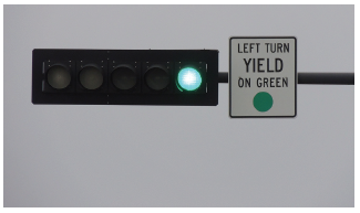
Figure 13. MUTCD R10-12 sign adjacent to left-turn signal face
Where practical, an additional R10-12 sign (i.e., in addition to the R10-12 sign adjacent to the signal face) should be placed in advance of the intersection to advise left-turning drivers of permissive signal operation. The sign should be displayed at a 3-s preview distance before the intersection, or at the beginning of the left-turn lane, as per engineering judgment, accompanied by an AT SIGNAL (R10-31P) supplemental plaque as shown in Figure 14. [See time-speed-distance table on page 5 of the Handbook.]
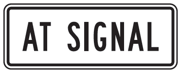
Figure 14. (MUTCD R10-31P)
A leading protected left-turn phase is recommended wherever protected left-turn signal operation is implemented (as opposed to a lagging protected left-turn phase).
The rationale and supporting evidence for these treatments begins on page 135 of the Handbook.
At signalized intersections where a right turn on red is prohibited, a supplemental NO TURN ON RED sign, using the MUTCD R10-11 design as shown in Figure 15, should be placed at a location on either the near or opposite side of the intersection where, per engineering judgment, it will be most conspicuous. This supplemental NO TURN ON RED sign is in addition to the MUTCD recommended practice of installing an R10-11 series sign near the appropriate signal head.
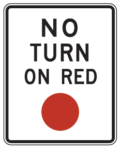
Figure 15. (MUTCD R10-11)
As discussed in Treatment 1: Intersecting Angle (Skew), at skewed signalized intersections where the approach leg to the left intersects the driver's approach leg at an angle of less than 75 degrees (as illustrated in Figure 4), prohibit right turn on red (RTOR).
The posting of MUTCD standard R10-15 signs, Turning Vehicles Yield to Pedestrians (shown in Figure 17) is recommended wherever engineering judgment indicates a clear potential for right-turning vehicles to come into conflict with crossing pedestrians. (Note that a yellow background color may be used instead of fluorescent yellow-green for this sign.)
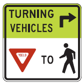
Figure 17. (MUTCD R10-15)
The rationale and supporting evidence for these treatments begins on page 148 of the Handbook.
To accommodate the reduction in visual acuity associated with increasing age, minimum letter heights of 6 in for uppercase letters and 4.5 in for lowercase letters are recommended for use on ground-mounted street-name signs (MUTCD D3-1, as shown in Figure 18) on all roads where the posted speed limit is at or below 25 mph. On all roads where the posted speed limit is greater than 25 mph, letter heights of 8 in for uppercase letters and 6 in for lowercase letters should be used.
The use of overhead-mounted street-name signs is recommended at major intersections as a supplement to ground-mounted street-name signs. Minimum letter heights of 12 in for uppercase letters and 9 in for lowercase letters are recommended by the MUTCD. In the design of street-name signs, the use of larger letter heights may require a larger sign panel. The border may be eliminated on street-name signs if necessary to minimize sign panel size while accommodating the larger letter size.
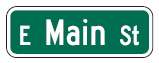
Figure 18. (MUTCD D3-1)
Wherever an advance intersection warning sign is installed (MUTCD W2 series) it should be accompanied by an advance street name plaque (W16-8P or W16-8aP) using minimum letter heights of 6 in for uppercase letters and 4.5 in for lowercase letters (see Figure 19). Where an advance traffic control sign (MUTCD W3 series) is installed on a multi-lane approach, an advance street name plaque (W16-8P or W16-8aP), using the same minimum letter heights described above, should be considered.
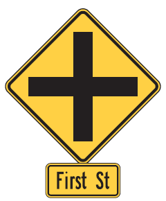
Figure 19. Intersection Warning W2-1 Sign and W16-8P Supplemental Advance Street Name Plaque
In the absence of an advance intersection warning sign or advance traffic control sign (with accompanying advance street-name plaque), the use of advance street-name signs (MUTCD D3-2) for major intersections is recommended, with turn bays to provide adequate preparation time for any lane change and/or turning maneuvers (see Figure 20).
When different street names are used for different directions of travel on a crossroad, the names should be separated and accompanied by directional arrows on both advance and intersection street-name signs, as shown in Figure 20.
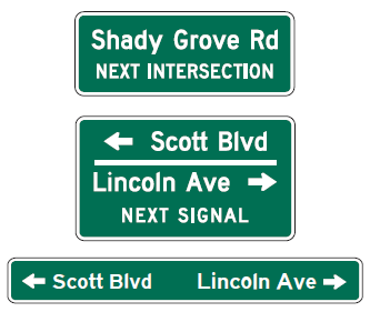
Figure 20. (MUTCD D3-2)
For ground-mounted street-name signs installed at intersections in areas of intensive land use, complex design features, and heavy traffic, prismatic retroreflective sheeting that provides for high retroreflectance should be used to provide increased sign conspicuity and legibility for aging drivers. The sheeting should be replaced well before it reaches the minimum levels designated in the current MUTCD (Section 2A.08 in the 2009 MUTCD).
The rationale and supporting evidence for these treatments begins on page 152 of the Handbook.
Treatments to improve the safe use of intersections by aging drivers, where the need for stop control or yield control has already been determined, include the following:
The use of standard size (30-in for single lane applications, 36-in for multi-lane applications) STOP (R1-1) and standard size (36-in for single lane applications, 48-in for multi-lane applications, 60-in for freeway applications) YIELD (R1-2) signs, as a minimum, is required by the 2009 MUTCD wherever these devices are implemented, with the option of using larger R1-1 (36-in for single lane applications, or 48-in in any location) signs where engineering judgment indicates that greater emphasis or visibility is required.
A minimum sign background (red area) retroreflectivity level (i.e., coefficient of retroreflection [RA]) for STOP (R1-1) and YIELD (R1-2) signs is as follows:
Signs with an RA below these levels should be replaced.
The use of a 30-in x 18-in supplemental warning sign panel (MUTCD W4-4P) as illustrated in Figure 21, mounted below the STOP (R1-1) sign, is recommended for two-way stop-controlled intersection sites selected on the basis of crash experience, where the sight triangle is restricted, and wherever a conversion from four-way stop to two-way stop operations is implemented.
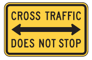
Figure 21. (MUTCD W4-4P)
A STOP AHEAD sign (MUTCD W3-1, as shown in Figure 22) should be used where the distance at which the STOP sign is visible is less than the AASHTO stopping sight distance (SSD) at the operating speed, plus an added preview distance of at least 2.5 s. [See time-speed-distance table on page 5 of the Handbook.]
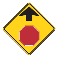
Figure 22. (MUTCD W3-1)
Utilize supplemental pavement markings on approaches to stop-controlled or yield-controlled intersections where engineering judgment indicates a special need due to sight restrictions, high approach speeds, or a history of ran-stop-sign crashes. "STOP AHEAD" pavement markings to supplement STOP AHEAD signs and triangular pavement markings to supplement YIELD AHEAD signs are described in MUTCD Section 3B.20 and Figure 32. Transverse pavement striping or rumble strips may also be considered where high approach speeds are a concern.
The rationale and supporting evidence for these treatments begins on page 160 of the Handbook.
The consistent overhead placement of lane-use control signs (MUTCD R3-5 and R3-6 series) at intersections on a signal mast arm or span wire is recommended, as illustrated in Figure 23.
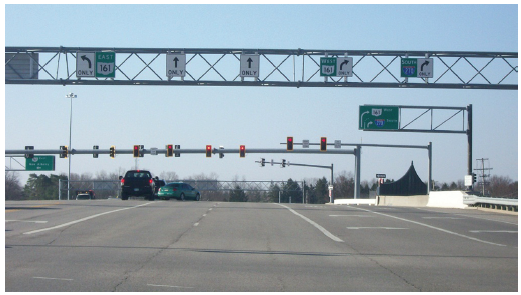
Figure 23. Mast-arm mounted lane-use control signs
The consistent posting of lane-use control signs (MUTCD R3 series) plus application of lane-use arrow pavement markings at a preview distance of at least 5 s (at operating speed) in advance of a signalized intersection is recommended, regardless of the specific lighting, channelization, or delineation treatments implemented at the intersection. [See time-speed-distance table on page 5 of the Handbook.] R3-5 and R3-6 series signs should be mounted overhead wherever practical.
The rationale and supporting evidence for these treatments begins on page 170 of the Handbook.
To ensure visibility and conspicuity of the traffic signal, the following is recommended:
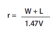
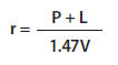
To accommodate age differences in perception-reaction time, an all-red clearance interval should be consistently implemented, with length determined according to the Institute of Transportation Engineers (2013) expressions given below:
B-1. Where pedestrian traffic is prohibited, or no pedestrian crossing facilities are provided, use:
B-2. Where pedestrian crossing facilities are provided, use:
where:
- r = length of red clearance interval, to the nearest 0.1 s.
- W = width of intersection (ft), measured from the near-side stop line to the far edge of the conflicting traffic lane along the actual vehicle path.
- P = width of intersection (ft), measured from the near-side stop line to the far side of the farthest conflicting pedestrian crosswalk along the actual vehicle path.
- L = length of vehicle (recommended as 20 ft)
- V = approach speed of the vehicle (mph)
Backplates with retroreflective borders should be considered as part of efforts to systemically improve safety performance at signalized intersections. Use backplates with traffic signals on all roads with operating speeds of 40 mph or higher. The use of backplates with signals is also recommended on roads with operating speeds lower than 40 mph where engineering judgment indicates a need due to the potential for sun glare problems, site history, or other variables. Yellow retroreflective borders, shown in Figure 24, may be used as an option to improve visibility of the illuminated face of the signal. The yellow retroreflective strip should have a minimum width of 1 inch and a maximum width of 3 inches and be placed along the perimeter of the face of a signal backplate to project a rectangular appearance at night. The yellow retroreflective strip should have a minimum width of 1 inch and a maximum width of 3 inches and be placed along the perimeter of the face of a signal backplate to project a rectangular appearance at night.
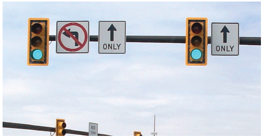
Figure 24. Yellow retroreflective backplates
The rationale and supporting evidence for these treatments begins on page 173 of the Handbook.
Wherever feasible, fixed lighting installations are recommended as follows:
Regular cleaning of lamp lenses, and lamp replacement when output has degraded by 20 percent or more of peak performance (based on hours of service and manufacturer's specifications), are recommended for all fixed lighting installations at intersections.
The rationale and supporting evidence for these treatments begins on page 181 of the Handbook.
To accommodate the aging pedestrian who typically has a shorter stride, slower gait, and delayed 'start-up" time before leaving from a position further back from the curb at signalized crossings, the joint application of the following practices is recommended:
For pedestrian crossings where the right-turn lane is channelized, it is recommended that:
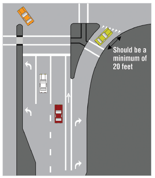
Figure 25. Pedestrian crossing at channelized right-turn lane
Where engineering judgment deems there to be a need to improve understanding of pedestrian signals, it is recommended that educational signs be posted near the crosswalk as follows:
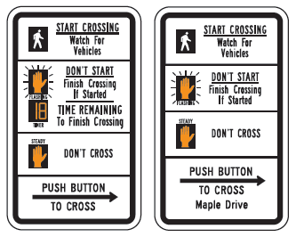
Figure 26. Figure 26. MUTCD R10-3 Series (R10-3e, R10-3f)
The posting of the MUTCD R10-15 sign (see Figure 27) is recommended wherever engineering judgment indicates a clear potential for right-turning vehicles to come into conflict with crossing pedestrians.
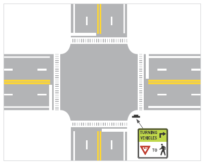
Figure 27. Recommended placement of MUTCD R10-15 sign
At intersections with high turning-vehicle volumes and no turn on red (NTOR) control for traffic moving parallel to a marked crosswalk, a leading pedestrian interval (LPI), timed to allow slower walkers to cross at least one moving lane of traffic is recommended to reduce conflicts between pedestrians and turning vehicles. The length of the LPI, which should be at least 3 s, may be calculated using the formula:

where:
Countdown pedestrian signals (see Figure 28) should be installed at all signalized intersections where pedestrian signals are warranted. The 2009 MUTCD requires the use of countdown pedestrian signals when the pedestrian change interval is greater than 7.0 s.
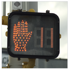
Figure 28. Countdown pedestrian signal
The rationale and supporting evidence for these treatments begins on page 185 of the Handbook.
Roundabouts should be considered as part of the engineering study in the design of new intersections and the redesign of existing intersections. When a State or local highway authority has determined through an engineering study to install a modern roundabout, include the following (see Figure 29):
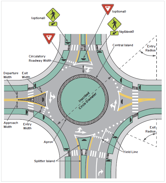
Figure 29. Key geometric design elements and traffic control devices for roundabouts
Unless required by operational needs, it is recommended that roundabout installations be limited to one-lane entrances and exits and one lane of circulating traffic.
Pedestrian crossings at single-lane roundabouts should be set back a minimum of 25 ft from the yield lines and include a crossing island of at least 6 ft in width.
To control for wrong-way movements, calm traffic, and provide a pedestrian refuge for all roundabout categories, raised splitter islands should be used, as opposed to pavement markings, to delineate the channelization. The pedestrian crosswalk area should be designed at street level (crosswalk cut through a splitter island).
To enhance the conspicuity of roundabouts in all categories, the sides and tops of curbs on the splitter islands and the central island should be treated with retroreflective markings, and be maintained at a minimum luminance contrast level* as follows:
The use of an advance roundabout warning sign (W2-6), as shown in Figure 30, is recommended on all approaches to a roundabout.
Figure 30. (MUTCD W2-6)
The use of a Roundabout Directional Arrow sign (R6-4 series) is recommended to direct traffic counter-clockwise around the central island. This sign display should be placed on the central island in direct view of a driver's entry point, as shown in Figure 31, (if different than at the centerline of the approaching roadway).
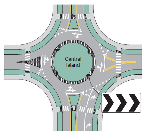
Figure 31. Roundabout directional arrow sign
The Roundabout Circulation Plaque (R6-5P) should be placed immediately below the R1-2 Yield sign on both sides of the road at each entrance to a roundabout (see Figure 32).
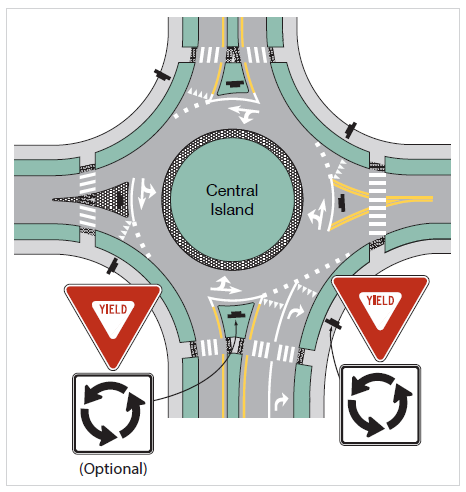
Figure 32. Placement of Roundabout Circulation Plaques
The rationale and supporting evidence for these treatments begins on page 197 of the Handbook.
Consider right-turn channelization with tighter turning radii to reduce turning speeds to approximately 17 to 18 mph, decrease pedestrian crossing distances, and optimize the right-turning motorists' line of sight, as shown in the Preferred example on the right of Figure 33. Traffic control devices at the end of the channelization should be visible to vehicles entering the channelized lane.
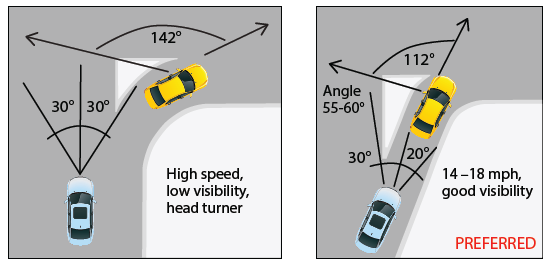
Figure 33. Right-Turn Channelization Design
The rationale and supporting evidence for these treatments can be found beginning on page 215 of the Handbook.
At intersections where complex design features or heavy traffic is present, and specific guidance advising roadway users which lane is necessary for their intended destination, combination lane use/destination signs (D15-1) should be used. These signs are typically used as overhead combination lane use destination guide signs and are described in Section 2D.33 of the 2009 MUTCD (see Figure 34).
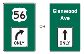
Figure 34. Combination Lane Use/Destination Guide Sign (MUTCD D15-1)
The rationale and supporting evidence for these treatments can be found beginning on page 215 of the Handbook.
Place all required signal heads overhead and centered over each lane instead of placing them on pedestal poles (see Figure 35). Supplemental signal heads may be placed on pedestal posts as needed.
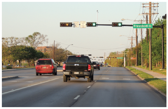
Figure 35. Example Of One Signal Head Per Lane
The rationale and supporting evidence for these treatments can be found beginning on page 216 of the Handbook.
To allow drivers to more easily see pedestrians in a marked crosswalk, high-visibility crosswalk marking patterns should be utilized. Two examples of such markings include white diagonal lines at a 45 degree angle to the crosswalk or the "ladder" crosswalk design shown in Figure 36.
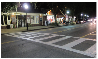
Figure 36. High-Visibility ("Ladder") Crosswalk
The rationale and supporting evidence for these treatments can be found beginning on page 216 of the Handbook.
Use "STOP AHEAD" word pavement markings to supplement stop ahead signs (W3-1) and "YIELD AHEAD" word pavement markings or yield ahead triangle symbol pavement markings to supplement yield ahead signs (W3-2). See Section 3B.20 of the 2009 MUTCD and Figure 37.
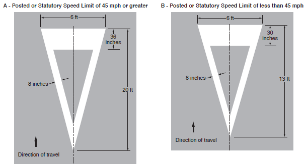
Figure 37. Yield Ahead Triangle Symbols
The rationale and supporting evidence for these treatments can be found beginning on page 217 of the Handbook.
A class of innovative intersection designs accommodate left-turns in unique ways, which greatly reduce, if not eliminate, unprotected left-turns at the intersection. Designs such as the median U-turn intersection (see Figure 38) and restricted-crossing U-turn (RCUT) intersection (see Figure 39) have features that minimize the operational delay and potential for crashes due to left turns. These innovative intersection designs should be considered for suitability during the engineering study for new and reconstructed intersections. Additional details are provided in the Handbook.
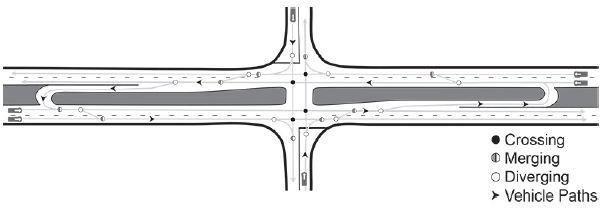
Figure 38. Diagram of Median U-Turn Intersection
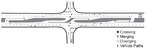
Figure 39. Diagram of Restricted Crossing U-Turn Intersection
The rationale and supporting evidence for these treatments can be found beginning on page 218 of the Handbook.
At crosswalks frequently used by aging pedestrians, consider inclusion of pushbutton-activated extension of the pedestrian crossing phase, using the required signage described by the MUTCD, as shown in Figure 40.
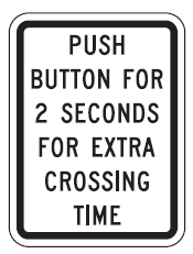
Figure 40. (MUTCD R10-32P)
Use of passive pedestrian detection to help aging pedestrians who have difficulty using the pushbutton or to detect pedestrians within the crosswalk that may need more time to complete the crossing maneuver. Passive pedestrian detection uses sensors to detect the presence of pedestrians and register a pedestrian call with the signal system; as a result, the pedestrian does not have to push a button to request a WALK signal or extended crossing time.
The rationale and supporting evidence for these treatments can be found beginning on page 219 of the Handbook.
The flashing yellow arrow (see Figure 41) is the recommended signal indication for permissive left-turn movements at signalized intersections.
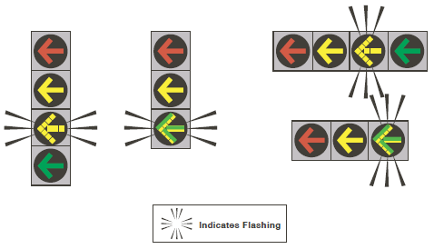
Figure 41. Typical arrangements of signal faces with flashing yellow arrow indications for permissive left-turn movements
The rationale and supporting evidence for these treatments begins on page 220 of the Handbook.