U.S. Department of Transportation
Federal Highway Administration
1200 New Jersey Avenue, SE
Washington, DC 20590
202-366-4000
The following discussion presents the rationale and supporting evidence for Handbook treatments pertaining to these two proven practices.
Proven Practices
For the approximately two-thirds of highway-rail grade crossings that are controlled by passive devices, "recognition errors" have been cited as the most frequent error type, accounting for 77 to 85 percent of the errors at Crossbuck-only crossings (Berg, Knoblauch, and Hueke, 1982). This category of driver error was defined broadly by the study authors as "a breakdown in the detection and/or perception of the necessary information to negotiate the crossing safely." Given the vast body of evidence that sensory and perceptual capabilities decline as a function of age, it is reasonable to assert that the tasks of detecting an approaching train and judging its distance and speed pose exaggerated difficulty for aging drivers. Older drivers are also slower than their younger counterparts to process information (Berg et al., 1982), which was cited as a significant contributing factor by these researchers in decision errors—i.e., the "breakdown in the analysis of information or an incorrect choice of action"—at rail crossings by elderly and inexperienced drivers. Fambro (1999) similarly underscores these problems which disproportionately affect aging road users in his comprehensive literature review, while summarizing a large body of research directed at engineering countermeasures to improve driver understanding of and behavior at grade crossings.
| Applications in Standard Reference Manuals | |||
|---|---|---|---|
| MUTCD (2009) | NCHRP 500 – Volume 9 (2004) | Railroad-Highway Grade Crossing Handbook (1986) | Traffic Engineering Handbook (2009) |
| Sect. 1A.13, Highway-Rail Grade Crossing Sects. 8A.01 & 8A.04 Figs. 8B-8 & 8B-9 Sects. 8B.03 through 8B.12 Fig. 8B-2, 8B-3 Sects. 8B.17, 8B.20 through 8B.23, 8B.27, 8B.28 Fig. 8B-4 Sects. 8A.06, 8B.16, 8B.19, 8B.26. |
Pg. 5-10, Sect. 5.2.6 Railroad-Highway Grade Crossings Pgs. 5-21 through 5-22, Sect. 5.3.6 Railroad-Highway Grade Crossings Pg. 6-10, Sect. 6.2.6 Railroad-Highway Grade Crossings Pg. 6-19, Sect. 6.3.6 Railroad-Highway Grade Crossings Pg. 7-26, Sect. 7.2.16 Railroad-Highway Grade Crossings Pg. 7-39, Sect. 7.3.7 Railroad-Highway Grade Crossings Pgs. 9-185 through 9-192, Sect. 9.12.3 Crossing Design |
Pg. 10, Para. 3 Pg. 11, Para 4 Pg. 12, Para. 2 Pg. 29, Para. 3 Pg. 30, Table 8 Pg. 31, Paras. 5-6 Pg. 33, Paras. 2 & 4 Pg. 53, Fig. 7 Pg. 57-58, Figs. 9-10 Pgs. 66-69, Sects. on New Hampshire Index & NCHRP 50 Pg. 71, Tables 19-20 Pg. 78, Para. 2 Pgs. 80-81, Para. 6 & Fig. 15 Pg. 83, Para. 5 Pg. 84, Para. 5, 4th bullet Pg. 87, Para. 4, Last bullet Pgs. 96-103, Sect. on Passive Traffic Control Devices Pgs.173-176, Item 1 of each economic type analysis Pgs. 177-180, Sect. on Resource Allocation Procedure Pg. 188, Para. 4 Pgs. 196-199, Part of Sect. on Traffic Control Devices Pgs. 201-202, Figs. 100-103 Pg. 206, Paras. 2-3 Pg. 215, Para. 4 Pg. 217, Para. 5 Pg. 219, Para 4, 2nd bullet Pg. 220, Sect. on Improved Signing Pg. 226, Paras. 4 & 8 Pg. 227, Para. 1 |
Pgs. 147, Table 5-7 Pg. 398, Item 1 Pg. 425, Final Paragraph Pgs. 634-635, Sect. on Railroad-Highway Grade Crossing Control |
Studies in this area have examined how changes in signing, delineation, the use of rumble strips and the introduction of nighttime illumination can variously affect drivers' allocation of attention; looking behaviors; braking/deceleration during approach to a highway-rail grade crossing; and maneuver decisions to negotiate the crossing; as well as the actual vehicle-train crash experience at a site.
To begin, simply detecting the presence of a passive crossing, where the need to slow and look for a train is indicated, can be problematic, especially at night. Fambro (1999) cites the work of Russell and Konz (1980) who found that placement of the Crossbuck sign (R15-1) does not make the best use of the vehicle's headlight beam pattern, which is aimed to the right and down. They state that certain combinations of headlight angle and roadway geometry at the crossing may result in a Crossbuck sign luminance of zero. The MUTCD states that the sign height above the ground (9 ft) may be varied as required by local conditions. Russell and Konz (1980) recommend lowering the Crossbuck by 2 ft, which would increase the illuminance by 50 percent at 150 ft and 69 percent at 250 ft. Russell and Rys (1994) conducted a small field study that confirmed that, from a distance of 350 ft, a Crossbuck at a height of 9 ft measured to the center and 6 ft from the right pavement edge received 8.4 percent of the vehicle headlight illuminance, compared to 14.2 percent if the Crossbuck were lowered to 7 ft above ground level, and 44 percent if the Crossbuck were lowered to 3 ft above the ground. Russell and Rys conclude that placement of the Crossbuck as low as possible and using retroreflective tape on the full length of the Crossbuck posts would make the best use of the greater headlight illuminance levels present near the ground.
Related work by Russell and Kent (1993) indicates that the conspicuity of passive grade crossings may be affected by adopting more effective delineation practices. These researchers conducted a before-after study to evaluate the effectiveness of five low-cost passive warning systems, implemented at six different sites. The warning systems included combinations of conventional signing (YIELD) and an enhanced delineation treatment; experimental signing (the "Buckeye Crossbuck," also termed the "Conrail Shield") as shown in Figure 96, plus an enhanced delineation treatment; two systems utilizing signing alone; and the enhanced delineation treatment alone. The enhanced delineation treatment included Type VII (ASTM D 4956-01) retroreflective tape that provides for high brightness on straight approaches as well as at wide observation angles (with SIA values ranging between 800 and 1,000), placed on both sides of both Crossbuck posts, and Type 2, flexible roadside retroreflective delineators with high intensity sheeting, placed on the right side of each approach, spaced 50 ft apart from the advance warning sign to the Crossbuck post (a total distance of 1,200 ft), and extending an equal distance beyond the Crossbuck post.
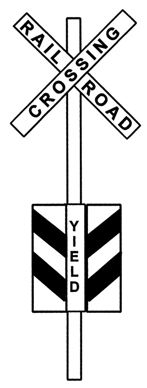
Figure 96. Experimental Enhanced Crossbuck Sign, Referred to as the "Buckeye Crossbuck" or "Conrail Shield"
The measures of effectiveness in the Russell and Kent (1993) study included: approach speeds; brake light activations; and head movements toward the tracks. One "before" study was conducted prior to installation of the new treatments, and two "after" studies were conducted, one at 2 months and the other at 7 months after treatment installation. Each observation period lasted for 3 to 4 days, from 2:30 p.m. until 5:30 p.m., and from 9:00 p.m. until 12 midnight. Results indicated that only the locations where the delineation system alone (roadside delineators and high-brightness tape on both sides of the crossbuck posts) was installed showed statistically significant, long-term positive changes in more than one variable (deceleration rates and looking behavior). The researchers indicated that the added retroreflective devices and tape on the Crossbuck posts provide high values of reflected light at all distances, especially under low-beam headlight conditions, concluding that the delineation treatment showed the most permanent improvement in driver behavior of the low-cost systems tested, and would be effective at grade crossings on highways in rural areas, particularly at night.
Brich (1995) similarly concluded that the use of very high intensity retroreflective sheeting (e.g., ASTM D 4956-01 Type IX) applied to both the front and back sides of the Crossbuck posts for the entire length of the post, plus double-sided Crossbucks (blades) also with very high intensity retroreflective sheeting resulted in superior conspicuity of the crossing, compared to systems that contained double-sided Crossbucks with Type IX sheeting, plus Type IX sheeting on only the back side of the posts (full length); or double-sided Crossbucks with Type IX sheeting, plus Type IX sheeting placed on the back of the posts in a 4-ft long strip; or single-sided Crossbucks with a strip of Type IX sheeting on the back side of the Crossbuck blades and also on the front and back of the posts (full length); or single-sided Crossbucks with a strip of Type VII sheeting on the back of the Crossbuck blades and also on the back side of the posts (applied 3 ft above ground level to the center of the Crossbuck blades). Both the Type VII and IX sheeting materials provide high brightness at wide observation angles, but Type IX is designed to provide high brightness at shorter viewing distances (in the 300- to 600-ft range). To delineate the Crossbuck posts, a strip of 2-in wide sheeting was applied to a 3-in wide, 9-ft tall aluminum strip that was mounted on the front and the back of the Crossbuck post, or to the back of the post only, depending on the treatment being evaluated. The study by Brich (1995) was conducted in a laboratory using videotaped images of varying treatments filmed under low- and high-beam headlight illumination at night, during the approach to rail grade crossings. A train was also filmed traveling through each crossing.
Comments obtained from the subjects in the Brich (1995) study indicated that marking the full length of the Crossbuck posts on the front and the back results in: (1) visually stabilizing the Crossbuck and tying it to the ground, which provides a valuable reference point; and (2) it makes the part of the far-side post below the undercarriage of a moving train in the crossing visible, causing a flickering effect that alerts a motorist of the presence of a train. It was concluded that using double-sided Crossbucks and marking the full length of both sides of both posts increases the visibility of the crossing; increases driver depth perception of the crossing; and increases the ability of a driver to detect a train in the crossing. The cost of a double-sided Crossbuck with Type IX sheeting in 1995 was $87.50 and the cost of sheeting and aluminum to apply to the post was $18.74 per Crossbuck assembly. Since most crossings use two Crossbuck assemblies, the cost per crossing (Crossbuck, post, aluminum strip, and retroreflective material) was $212.48, in 1995 dollars.
The MUTCD (FHWA, 2009) includes the requirement to use a strip of retroreflective sheeting that is at least 2-in wide, on the front and back of each Crossbuck support post, for the full length of the post. In addition, it states that a strip of retroreflective sheeting shall be applied to the back of the Crossbuck blades, except in locations where Crossbuck signs are installed back-to-back.
The largest body of work has been directed toward improving performance under daytime conditions, seeking to improve conspicuity for advance warning devices as well as devices at the crossing, but principally focusing upon motorists' understanding of signs at highway-rail grade crossings. Uses of novel sign designs, combinations, materials, and placements have been evaluated, plus expanded applications of conventional devices—particularly STOP signs.
Research has indicated that driver comprehension of highway-rail grade crossing signs is poor. Even when the signs are conspicuous, they don't provide any information about what drivers should do when approaching or crossing the tracks. The MUTCD (2009) specifies that a railroad crossing sign (Crossbuck, R15-1) is a regulatory sign, and indicates that as a minimum, one sign shall be used on each roadway approach to every grade crossing, alone or in combination with other traffic control devices. Although the Crossbuck is, in effect, a YIELD sign, and motorists have the obligation to so interpret it, drivers do not have a clear understanding of what their responsibilities are when encountering the Crossbuck sign (Fambro et al., 1997). Lerner, Ratte, and Walker (1990) indicate that across studies, the majority of subjects (54 to 84 percent) believe that the appropriate behavior at a passive crossing is to stop; however, observational studies indicate that drivers routinely disregard this "rule."
One area of research has attempted to enhance the conspicuity and comprehensibility of the Crossbuck sign. Two enhanced Crossbuck signs have been evaluated in the State of Ohio (Zwahlen and Schnell, 2000). The Buckeye Crossbuck (also known as the Conrail Shield) is a standard Crossbuck sign with a supplemental reflectorized aluminum shield with a red vertical YIELD legend, mounted at headlight level. The 38-in high shield (reflectorized with white microprismatic sheeting on both sides) contains a 9-in wide center section (YIELD) with two 12-in side panels that are bent away from the center panel at 45-degree angles (see Figure 96). These panels contain alternating stripes of red and white highly retroreflective sheeting, with narrow mirrored strips between the stripes. This device costs approximately $300 per crossing. The Buckeye Crossbuck and the Standard Improved Crossbuck were evaluated on a statewide basis in Ohio with respect to their potential to alter driver risk taking behavior, their crash reduction potential, user acceptance, and photometric performance at night. The Standard Improved Crossbuck consists of a wooden post that is reflectorized on all four sides and aluminum blades that are reflectorized on both front and back with white microprismatic long-distance performance (Type VII) sheeting and the standard black legend. The Standard Crossbuck consists of a non-reflectorized wooden post and aluminum blades equipped with white encapsulated retroreflective sheeting material (Type III) and the standard black legend.
For the driver risk-taking portion of the study, motorist near-collision and violation video data were collected along four selected rail corridors during 1995 in the before-condition (Standard Crossbuck condition). In the after-condition (1996-1997) half of the Current Standard Crossbucks were replaced with the Buckeye Crossbuck and the other half were replaced with the Standard Improved Crossbuck. A total of 3,833 passive railroad crossing approaches were recorded under both the before and after condition. Motorists were categorized as either compliant (yielded to an approaching train blowing its whistle) or non-compliant (drove over the crossing although an approaching train was blowing its whistle). Results of the driver risk-taking study indicated that the new crossbuck devices did not provide increased compliance over the standard crossbuck (56.1 percent non-compliant vs. 54.6 percent non-compliant). However, none of the driver violations in the before or after period were closer than 5 seconds. Both new crossbuck designs provided temporal distributions that were slightly shifted towards longer risk acceptance times (median value = 25 seconds) when compared to the temporal distributions obtained with the Current Standard Crossbuck design (median value = 20 seconds). The increased time difference for the Buckeye Crossbuck compared to the Standard Crossbuck was significantly significant (p<0.0186). The crash analysis showed a statistically significant superiority (p<.0.047) of the Buckeye Crossbuck (157 crashes) over the Standard Improved Crossbuck (192 crashes) from 1994 to 1999, a 22.3 percent decrease. The crash analysis included every public passive railroad/highway grade crossing in Ohio; all crossings were equipped with either the Buckeye Crossbuck or the Standard Improved Crossbuck, which were evenly matched in terms of their number of installations. The user acceptance survey included 374 returned surveys out of 1,009 sent to randomly sampled licensed Ohio drivers. Findings indicated an overwhelming preference of the Buckeye Crossbuck over the Standard Improved Crossbuck. The majority of road users perceived that the additional area of the shield with the vertical "Yield" legend was useful in warning an approaching driver about the presence of a public passive railway/highway crossing. Road users indicated that the Buckeye Crossbuck should be adopted as a warning device at public passive crossings. The Buckeye Crossbuck provided the strongest visual signal among the measured crossbucks at night and during the day.
Based on their study findings, Zwahlen and Schnell (2000) recommended amending the National standard for crossbucks at passive railroad/highway grade crossings in the MUTCD, including the Buckeye Crossbuck as an alternative design, with the following modification. They recommended that the sheeting material of choice for the whole Buckeye Crossbuck should be a microprismatic sheeting material with a high angularity (Type VII Visual Impact performance, instead of Type VII Long Distance Performance).
Bridwell, et al. (1993) conducted a laboratory study that employed 42 young/middle-aged subjects (ages 25 to 45 years) and 42 older subjects (ages 65 to 85) who viewed slides of 7 railroad crossing signs. The signs included the standard Crossbuck sign (R15-1); the standard Crossbuck sign with a red and white striped (barber) pole; the standard Crossbuck sign with a standard YIELD sign mounted below; the standard Crossbuck with the Conrail Shield mounted below; the Canadian Crossbuck (Crossbuck with white panel, red border, and no text); the Canadian Crossbuck with the Conrail Shield mounted below; and a standard YIELD sign with a black and white regulatory sign below reading "TO TRAINS." Sign recognition distance, conspicuity distance (except for the YIELD TO TRAINS sign) and driver comprehension data were collected. Although there were no significant differences in recognition distance between the signs, the authors suggest that this may be more a result of the testing conditions (laboratory) than of the signs themselves. They recommend that a field study be conducted to measure actual recognition distances. In terms of conspicuity distance, the worst performing signs were the two that contained only the Crossbuck (standard R15-1 and the Canadian Crossbuck). The standard Crossbuck when supplemented with the YIELD sign, or the Conrail Shield, or a barber-striped pole was noticed significantly more often.
For the comprehension portion of the Bridwell et al. (1993) study, drivers were asked about what they thought the sign meant, and what they should do if they encountered such a sign on the roadway. Drivers who didn't know what the meaning of a sign was (i.e., "there is a railroad crossing") were shown the Advanced Railroad Crossing (W10-1) warning sign to help put the Crossbuck sign "in context." Several drivers required this "in context" information to correctly identify the meaning of the Canadian Crossbuck, the Canadian Crossbuck with the Conrail Shield, and the YIELD TO TRAINS sign. Data were therefore presented for percent-correct for sign meaning before and after being shown the Advance Railroad Crossing sign. Responses were always correct (100 percent comprehension) before the Advance sign for three of the signs: the standard Crossbuck, the standard Crossbuck sign with the barber pole, and the standard Crossbuck with the YIELD sign. For the other four signs, the "before" data for percent correct responses were as follows: standard Crossbuck with Conrail Shield (83.3 percent), Canadian Crossbuck (91.7 percent); Canadian Crossbuck with Conrail Shield (58.3 percent); and YIELD TO TRAINS sign (66.7 percent). After presentation of the Advanced Railroad Crossing sign, comprehension improved for three signs: all drivers understood the meaning of the Canadian Crossbuck and the YIELD TO TRAINS sign (100 percent correct comprehension), and comprehension improved from 58.3 percent correct to 83.3 percent correct for the Canadian Crossbuck with the Conrail Shield. In terms of knowing what to do when encountering such a sign, the two best signs (83.3 percent correct for the standard Crossbuck with the YIELD sign and the YIELD TO TRAINS sign) significantly outperformed the two worst signs (the standard Crossbuck [41.6 percent correct] and the Canadian Crossbuck [33.3 percent correct]). The other three signs were understood correctly half of the time. After being shown the Advance Railroad Crossing sign, the only sign that showed significant improvement in driver understanding of the correct action was the YIELD TO TRAINS sign, which increased to 100 percent identification of the correct action.
Bridwell et al. (1993) conclude that a change in the current standard Crossbuck sign for passive crossings appears necessary, based on study findings that it is neither well understood nor well noticed. They recommend further testing in the field for the standard Crossbuck sign supplemented with the standard YIELD sign, the standard Crossbuck sign supplemented with the Conrail Shield (which has the words "YIELD"), and the standard YIELD sign with the supplemental plaque that reads "TO TRAINS." The Canadian Crossbuck should be omitted from further testing, as it performed worse than the standard Crossbuck.
Fambro (1999) conducted five focus groups containing 10 participants each, who were selected to provide a range of ages. Focus groups were conducted in College Station, Corsicana, and Arlington, Texas and in De Kalb and St. Charles, Illinois. During the sessions, participants were asked to provide their reactions to the following eight traffic control devices described as proposed enhancements to passive warning devices at highway-rail grade crossings: (1) Buckeye Crossbuck; (2) LOOK FOR TRAINS sign; (3) YIELD TO TRAINS sign; (4) a vehicle-activated strobe light; (5) illumination; (6) rumble strips; (7) additional retroreflective material and/or devices on Crossbuck and support posts; and (8) roadway traffic signals. None of the passive signing systems were recommended by focus group participants as promising, although the Buckeye Crossbuck was rated as an excellent alternative in one of the five focus groups.
In the Fambro et al. (1997) survey of 1,010 drivers conducted to determine driver understanding of traffic control devices at highway-rail crossings, 82 percent of the respondents correctly identified the meaning of the "YIELD TO TRAINS" experimental sign (i.e., "Yield the right-of-way if a train is approaching a crossing"). In the focus group sessions conducted by Fambro (1999), the "YIELD TO TRAINS" signs were not rated as promising alternative traffic control devices. However, he recommends their use at passive grade crossings in rural areas, to alert and warn drivers that they are approaching a critical safety decision point. The sign consists of a standard YIELD sign, with a supplemental panel with the phrase, "TO TRAINS." The sign combination can be placed on the standard Crossbuck sign or used on a separate pole at the crossing. Fambro's recommendation is based on a before-after study conducted in Texas, which found a significant decrease in approach speed at two of six sites; significant increases in looking behavior at three of eight sites; and no significant decrease in looking behavior at any of the eight sites evaluated (Fambro, Beitler, and Hubbard, 1994).
The above recommendations with combinations involving the standard R1-2 sign focuses attention on the use of traffic control devices whose meanings are familiar to drivers. Section 8B.04 of the MUTCD (2009) indicates that, while the Crossbuck Assembly is required, STOP or YIELD signs may be used in addition to the Crossbuck Assembly at passive grade crossings at the discretion of the responsible State or Local jurisdiction. It further states that a YIELD sign shall be the default traffic control device for Crossbuck Assemblies on all highway approaches to passive grade crossings unless an engineering study performed by the regulatory agency or highway authority having jurisdiction over the roadway approach determines that a STOP sign is appropriate. Engineering studies should take into account such factors as the line of sight to approaching rail traffic (giving due consideration to seasonal crops or vegetation beyond both the highway and railroad or LRT rights-of-ways), the number of tracks, the speeds of trains or LRT equipment and highway vehicles, and the crash history at the grade crossing. The YIELD or STOP sign may be installed on the same support as the Crossbuck sign or it may be installed on a separate support; in either case the YIELD or STOP sign is considered to be a part of the Crossbuck Assembly.
The use of STOP signs at passive crossings has been a controversial issue for over 40 years (Russell and Burnham, 1999). One camp (including Russell and Burnham) maintains that the indiscriminate use of STOP signs at all passive crossings would serve to breed driver disrespect for STOP signs as well as for highway-rail grade crossings. Russell and Burnham (1999) cite the research of Bezkorovainy-Holsinger (1966) and Burnham (1994) who observed that approximately 84 percent of drivers at STOP-controlled highway-rail grade crossings violated the law, and either did not stop at all, or performed a rolling stop.
This view is contrasted against that of the National Transportation Safety Board (NTSB), who in 1998 recommended that States install STOP signs at all passive grade crossings unless a traffic engineering analysis determines that installation of a STOP sign would reduce the level of safety at a crossing. Farr and Hitz (1985) found that STOP signs reduced crossing crashes by approximately 35 percent, based on analysis of data included in the Department of Transportation (DOT)-Association of American Railroads (AAR) Rail-Highway Crossing Inventory and the Federal Railroad Administration (FRA) Railroad Accident/Incident Reporting System for the years 1975 through 1980. Eck and Shanmugam (1987) used the National Rail-Highway Crossing Inventory and FRA crash files to compare low-volume road grade crossing characteristics with high-volume road grade crossing characteristics. They found that exposure-based crash rates at low-volume road grade crossings were much higher than at higher-volume road grade crossings, and that magnitudes of crash reductions following upgrades from no signs or Crossbucks only to STOP signs were higher for the low-volume crossings.
Earlier work in this area has also influenced current thinking, particularly the Sanders, McGee, and Yoo (1978) study which determined advantages and disadvantages of the selective use of highway STOP signs as safety improvements at highway-rail grade crossings, and developed guidelines for their use. They performed crash analyses to compare crash rates for crossings with Crossbucks only to crash rates for crossings with Crossbucks and standard highway STOP signs. Results indicated that crash rates for STOP-sign crossings were lower than rates for Crossbuck-only crossings, given higher vehicle-train exposure. Sanders et al. (1978) also performed field studies to compare driver behaviors for Crossbuck-only crossings to driver behaviors for similar crossings where a standard highway STOP sign was installed in addition to the Crossbuck. Driver behaviors included looking behavior, speed profiles, and observance of STOP signs. Looking behavior was obtained by Sanders et al. (1978) for 1,413 drivers at 8 Crossbuck-only sites in 4 States, and for 3,073 drivers at 18 sites with both a STOP sign and a Crossbuck sign in 5 States. They found that 83 percent of the drivers looked for trains at the locations with STOP signs, but only 42 percent looked for trains at the Crossbuck-only sites. Speed profile measures indicated that drivers approaching a STOP-sign crossing began their deceleration closer to the crossing than did drivers approaching a Crossbuck crossing. Also, vehicle speeds just prior to the crossing were considerably lower at the STOP-sign crossing. Sanders et al. (1978) observed that while STOP sign observance (compliance) at stop-controlled highway-rail crossings was less than at highway intersections (60 percent vs 80 percent), there was no transfer of adverse stopping behavior between the rail-grade crossing and a nearby stop-controlled highway intersection.
Applying the results of Sanders et al. (1978) to the goal of accommodating age-related driver difficulties is hampered by lack of knowledge about the age of drivers sampled in their research. In addition, the driver behaviors adopted as outcome variables were affected by factors other than signing practices and site characteristics. For example, looking behavior was affected by the level of enforcement at STOP sign controlled crossings. Their principal conclusion still is worth noting: STOP signs should be applied selectively only at hazardous passive grade crossings (restricted sight triangle; ADT<2000; 3+ train crossings per day) and should not be used indiscriminately at all passive grade crossings.
Fambro, et al. (1997) conducted a field study using 10 younger drivers (ages 18 to 25), 10 middle-aged drivers (ages 30 to 45), and 10 older drivers (ages 55 and older), to document looking behavior and deceleration at rail grade crossings. This study was predicated upon the belief that looking behavior in both directions and a significant reduction in speed are the key safety goals at passive crossings, because no warning devices are activated when a train is approaching the crossing. The passive site with the greatest percentage of drivers who looked in both directions before crossing (97 percent) was a site controlled by a STOP sign. All of the young and middle-aged drivers looked both ways at this site, and 9 of the 10 older drivers looked both ways. Three of the 30 drivers did not stop at the STOP sign (although they slowed considerably), and 10 drivers performed a rolling stop. At the other two passive sites (marked with Crossbuck signs only, and no advance railroad crossing sign), 70 percent of the drivers did not look in both directions at one site (70 percent of younger, 80 percent of middle-aged, and 60 percent of older drivers), and 17 percent did not look in both directions at the other site (20 percent of the younger, 10 percent of the middle-aged, and 20 percent of the older drivers).
It may be noted that stopping before reaching the tracks provides the driver who may have difficulty dividing attention (e.g., the aging driver), with the ability to focus on the single task of looking for a train. For example, Lerner, Ratte, and Walker (1990) note that in the Knoblauch et al. (1982) study, relatively few crashes occurred at a roadway-rail grade crossing because a driver who was stopped (at a passive crossing or at an active crossing with flashing lights) misjudged a gap and proceeded to cross. The large majority of decision errors were made by drivers in moving cars. Expecting to stop and seeing a STOP sign at a passive crossing would also remove the potential for vehicle-to-vehicle (rear-end) crashes. Related is the fact that 15 to 25 percent of drivers expect all crossings to be actively controlled (Fambro, 1999; Lerner et al., 1990). This erroneous perception results in drivers assuming that it is safe to cross (without slowing or looking both ways) when there are no lights flashing, even when there are no lights present at the crossing. A STOP sign at a passive crossing will eliminate this expectancy and provide positive and unambiguous guidance, removing the need to look for the absence of active warnings for clues about what behavior is appropriate. Also, as Lerner et al. (1990) note, response time is faster to detect the presence of a TCD as opposed to its absence.
Together, the findings and conclusions in the paragraphs above should provide guidance for the selective use of the R1-1 sign at highway-rail grade crossings, by informing the engineering judgment called out in the MUTCD for application of these devices.
As described in Part I (Treatment 11 Stop and Yield Signing), highway signs with fluorescent sheeting have been found to be more conspicuous and can be detected at a further distance than signs with standard sheeting of the same color. Of particular interest is a study by Burns and Pavelka (1995), who found that signs with fluorescent red sheeting had greater detection and color recognition distances at dusk than signs made with standard red sheeting. The results of this study suggest that the use of fluorescent red sheeting on YIELD signs at highway-rail grade crossings (and on STOP signs, where they are deemed appropriate), would serve to increase their conspicuity both under daytime and low luminance conditions, and would be of particular benefit to aging drivers, who suffer from decreases in contrast sensitivity.
Other research pertaining to signing for highway-rail grade crossings for which data from aging drivers has been obtained has addressed comprehension of the Railroad Advance Warning sign and the Parallel Railroad Advance Warning sign. Picha, Hawkins, and Womack (1995) conducted a survey of 747 drivers ranging in age from 16 to 65 and older who were renewing their drivers' licenses in seven Texas cities. Of the 747 participants, 54 were ages 55 to 64 (7.3 percent of the sample) and 31 were age 65 or older (4.2 percent of the sample). A multiple choice question was included regarding the meaning of the W10-1 (Railroad Advance Warning) sign and the W10-3 (Parallel Railroad Advance Warning) sign. No advantages for alternative designs to the standard W10-1 were demonstrated in this research; however, an alternative to the current W10-3 was recommended.
The standard Parallel Railroad Advance Warning sign (W10-3) and three Alternative designs were shown to the same driver sample. (See Figure 97.) Alternative 1 was a yellow diamond sign that consisted of the same elements present in the standard design, except that the roadway outline was drawn (as opposed to thick solid lines), and a bent right arrow was drawn within the roadway lines to indicate that a right turn would lead to railroad tracks. Alternative 2 was the standard W10-1 sign (Advance RR Crossing) with a supplemental plaque containing an arrow that pointed to the right. Alternative 3 was the same as Alternative 2 except the supplemental panel contained a bent right-pointing arrow. The correct response, "you will cross a railroad track if you turn right at the intersection," was provided by 84.1 percent of the participants who saw the standard sign; 88.1 percent of the respondents who saw Alternative 1; 90.5 percent of the respondents who saw Alternative 2; and 87.2 percent of the respondents who saw Alternative 3. A higher percentage of respondents indicated that they did not know what the standard sign meant (10.2 percent) than the alternative designs (6.2 percent for Alternative 1; 3.2 percent for Alternative 2; and 1.6 percent for Alternative 3). Thus, the standard W10-3 sign had the lowest correct response rate and the highest "not sure" rate, although these differences did not reach statistical significance. While suggestive, further work is deemed necessary to justify a treatment in this Handbook.
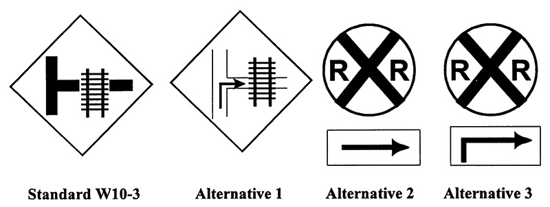
Figure 97. Standard MUTCD W10-3 Sign and Alternative Sign Designs Evaluated by Picha, Hawkins, and Womack (1995)
The next category of countermeasures reviewed, targeting speed reductions by drivers approaching highway-rail grade crossings, is the application of rumble strips. Fambro's (1999) review indicates that in Kentucky, rumble strips were effective in reducing collisions and near misses, with no indication of motorists avoiding the rumble strips; however, in Georgia, about 12 drivers per day "drove around" the strips (Skinner, 1971; Parsonson and Rinalducci, 1982). Parsonson and Rinalducci (1982) recommend that at grade crossings, rumble strips should be applied only at nonresidential locations where unfamiliar drivers are the prevalent group. Fambro states that the potential benefits of rumble strips at roadway-rail grade crossings include: decreased approach speeds; increased awareness of warning signs; and increased awareness of a potentially hazardous intersection. He recommends their use for passive crossings on rural, low-volume roadways and provides the following guidelines:
Three to four rumble strip pads of 5 to 20 rumble strips should be used, with the first pad placed 2 to 3 s before the advance warning sign to direct the driver's attention to the sign.
Subsequent pads should be placed with decreasing spacing and numbers to create the sensation of acceleration.
The last pad should be placed at least 250 ft before the crossing to avoid creating a pavement condition that might interfere with braking.
Another view is provided by Lerner, Ratte, and Walker (1990), who caution that distorting the driver's perception of approach speed with progressively decreasing spacings of rumble strips, in an effort to encourage slowing on the approach to a crossing, could actually encourage a driver to speed up and try to beat a train. While this behavior has not typically been associated with aging drivers either in the research literature or anecdotally, it raises a more general concern that any present recommendation regarding the use of rumble strips would be premature.
Finally, a novel treatment to attract motorists' attention to highway-rail grade crossings is the use of a vehicle-activated strobe light on a sign assembly. The vehicle-activated strobe light causes short bursts of flashing light when a vehicle passes over detectors placed in the roadway. In research conducted by the Texas Transportation Institute, the strobe is mounted on top of a standard railroad advance warning sign, and the vehicle detector is placed approximately 8 seconds before the advance warning sign (Fambro, Schull, Noyce, and Rahman (1997). The strobe flashes three to five times to direct the driver's attention toward the advance warning sign, and it should stop flashing 2 to 3 seconds before the driver reaches the sign to allow time to read the sign.
Fambro et al. (1997) evaluated this treatment in a controlled field study using 7 younger drivers (age 25 or younger), 12 middle-aged drivers (ages 25 to 54) and 7 older drivers (age 55 and older). Head movements toward the sign and braking reactions were recorded by in–vehicle observers to the advance railroad crossing sign alone, to the advance railroad crossing sign supplemented with a strobe light, and to an advance railroad warning sign supplemented with a standard flashing beacon. The sign sheeting was engineering grade, making it retroreflective. There were no differences in head movements (indicating no differences in attention-getting value) as a function of the sign system; however, 54 percent of the drivers exhibited braking in response to signs enhanced with either the strobe light or the flashers, compared to 31 percent who exhibited braking to the standard sign without enhancements. Drivers also responded to a questionnaire and participated in a focus group discussion. Three drivers (11 percent) thought that the strobe-enhanced sign indicated that a train was ahead, and 9 drivers (35 percent) thought that the flashing beacon indicated the presence of a train. The authors mention a concern with this interpretation; drivers at passive crossings who do not see trains approaching after encountering strobe- or flasher-enhanced warning signs may begin to disrespect active devices at crossings that do indicate the presence of a train. Seven drivers (27 percent) indicated that the strobe light was confusing, and 11 drivers (42 percent) thought the flasher-enhanced sign was confusing. With special attention to the problems of aging drivers, including the difficulties in decision making and delays in response time when confronted with unusual or unexpected situations, such results were not sufficiently encouraging to warrant a recommendation in this Handbook.
Aging drivers, with their decreased contrast sensitivity, and need for increasing levels of light for night driving tasks, would be expected to benefit disproportionately from increasing the detectability and conspicuity of railroad crossing signing, and of the crossing itself. Another strategy is to add illumination to passive crossings. In one before-after study of 52 highway-rail grade crossings (Russell and Konz, 1980), adding illumination to passive crossings resulted in an 85 percent reduction in the mean number of crashes per week (where the vehicle ran into a train already at the crossing). The importance of illumination at passive highway-rail grade crossings was also highlighted by Fambro (1999).
Mather (1991) evaluated the 7-year crash history of 35 passive highway-rail grade crossings in Oregon that were illuminated as a low-cost alternative for improving crossing safety at night. The eligibility criteria for the installation of illumination were: (1) the crossing must have regular nighttime train movements (4 p.m. to 7 a.m.), and (2) the crossing is too low on the statewide crossing priority list (low train or vehicle traffic volumes) to qualify for automatic warning devices. Crash data indicate that before illumination, 18 train-vehicle crashes occurred at 13 crossings during the hours of darkness. After illumination, only 3 train-vehicle crashes occurred at two crossings during the hours of darkness.
The cost of installation across the 34 crossings averaged $1,931 per crossing, and ranged from $386 to $9,384 (where a 1-mi long ditch was dug to provide electrical power to the site). The goal was $2,000 per crossing (a substantial reduction of the costs associated with installing active warning devices, estimated to be in excess of $100,000 per crossing, according to Bridwell et al., 1993). Monthly maintenance costs averaged $15 per luminaire per pole.
The installation specifications for illumination at the crossings reported on by Mather (1991) are as follows.
At least one luminaire shall be mounted on each side of the track at the crossing. Luminaires should be located so that protective devices at the crossing will be directly illuminated.
Luminaires shall be oriented toward the railroad track to provide at least 10.76 lux [1 footcandle (fc)] of illumination on the vertical plane 5 ft from the centerline of the track. Maximum permissible level of illumination and exact orientation of the luminaire will be determined on a case-by-case basis. Factors at the site, including the ambient level of nighttime illumination, need to be considered. The maximum level of illumination is related to the level of lighting on the roadway approaches. The level of illumination should be sufficient to alert drivers to the crossing ahead and to any railroad equipment occupying the crossing, but should not be so bright as to create a blinding effect for motorists in the area immediately beyond the crossing. Cutoffs will normally be used on luminaires to minimize this blinding effect.
| Applications in Standard Reference Manuals | ||
|---|---|---|
| MUTCD (2009) | NCHRP 500 – Volume 9 (2004) | Traffic Engineering Handbook (2009) |
| Pgs. V-22-V-23, Sect. on Strategy 3.1 B8: Improve Roadway Delineation (T) | Pgs. 55-56, Sect. on Control of Distribution Above Maximum Candlepower | Pgs. 140-143, Sects. on Illumination & Miscellaneous Improvements |
Luminaires should illuminate an area along the track that is 50 percent wider than the traveled width of the road. The illumination should cover a distance equal to the normal height of rail equipment (at least 15 ft above the top of the rail).
Poles holding luminaires should be located so that they can be maintained from the roadway right-of-way.
Mather (1991) states that it was difficult to convince highway authorities and electrical companies that the luminaires should be aligned toward the railroad tracks instead of the roadway. However, through meetings and demonstrations, all parties eventually agreed that the luminaires were more effective if they were aligned toward the track. Light readings taken at all tracks showed that a higher percentage of the installations complied with the 10.76 lux (1 fc) standard for illumination where the luminaires faced the railroad tracks. Mather provided the following specifications for the installations. For single-track crossings, poles were located 25 ft from both the road and the centerline of the railroad track. Two-hundred-watt, high-pressure sodium luminaires were placed at least 30 ft above the top of the rail on 6- to 16-ft long arms. If a railroad signal system was involved, full cutoff luminaires were used. For multiple-track crossings, 400-watt, high-pressure sodium luminaires were placed at least 40 ft above the top of the rail. If a considerable distance separated the tracks, it was desirable to install a luminaire between the tracks. Semicutoff luminaires were used because they spread the light over a larger area of the crossing. This treatment was needed at crossings with three or more tracks, and those with severe angles of intersection.

