U.S. Department of Transportation
Federal Highway Administration
1200 New Jersey Avenue, SE
Washington, DC 20590
202-366-4000
| < Previous | Table of Contents | Next > |
Roadway departure crash rates are three times higher at horizontal curve locations relative to tangent segments of roadway. Sequential Dynamic Curve Warning Systems (SDCWS) have been implemented as a countermeasure on two-lane rural highway curves as a means to reduce vehicle operating speeds and improve curve delineation. The anticipated benefit of implementing SDCWS is reductions in total and severe crashes.
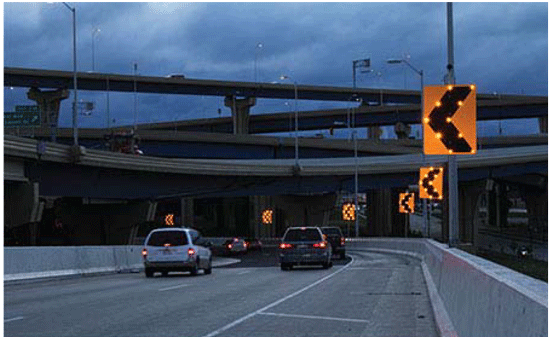
SDCWS are horizontal curve chevron signs with solar powered flashing lights embedded in the sign. The flashing lights can be simultaneous (i.e., each sign is flashing at the same time as the other signs); or, more often, there may be a pattern associated with the flashing lights (i.e., a sequence of lights moving toward or away from the driver). In the latter case, this is typically accomplished by having each sign flash at least once per second, with each flash lasting at least 100 milliseconds. Each sign begins flashing at a time that is offset relative to the adjacent sign, producing a sequential flashing effect.

Figure E-1. Photo. SDCWS.
The States of Missouri, Texas, Washington, and Wisconsin collectively installed 12 TAPCO SDCWS's along horizontal curves on two-lane rural highways as part of an FHWA Highways for Life evaluation. Because there were only 12 SDCWS locations included in the study sample, only one manufacturer's product was selected for implementation in the evaluation to ensure consistency in system design and application. The TAPCO system was selected as a typical representation of SDCWS's. The study sites were identified based on a high-crash history, as well as vehicle operating speeds that exceeded the advisory (if present) or posted speed limit.
All curves selected for treatment with SDCWS were on a two-lane rural paved road and have the following:
All installations of SDCWS at the curves occurred between June and September of 2012. A total of 24 similar horizontal curves in the same States were used as a control group, without SDCWS.
Speed data were collected before installation, and 1, 12, 18, and 24 months after installation of the SDCWS. Crash data were also compiled for each of the SDCWS and control sites, including five years before and two years after implementation.
The results showed that vehicle operating speeds were lower at the beginning and midpoint of horizontal curves for all periods after the SDCWS were installed. The mean and 85th percentile speeds were 1.1 to 1.7 mph lower in the 1, 12, 18, and 24 month periods after installing the SDCWS. The results were generally consistent when comparing speeds at the beginning and the midpoint of horizontal curves. The percentage of vehicles exceeding the posted and advisory speed limits was also lower after installing the SDCWS, and results were generally consistent across all time periods after implementation. The change in the fraction of vehicles exceeding the advisory speed by 20 mph or more decreased by an average of 32 percent at the beginning of the horizontal curve. Similarly, the change in the fraction of vehicles exceeding the advisory speed by 15 mph or more decreased by an average of 30 percent at the beginning of the horizontal curve. The fraction of vehicles exceeding the advisory speed by 20 mph or more at the midpoint of the curve decreased by 26 percent, while the fraction of vehicles exceeding the advisory speed by 15 mph or more declined by 16 percent after SDCWS installation. The results of the study suggest that SDCWS have long-term and consistent effect on vehicle operating speeds. While the magnitude of the effect was relatively small, there was a pronounced effect on those vehicles substantially exceeding the advisory speed.
With regards to safety, a simple before-after analysis of crash data found that the total number of crashes per year declined by 17 to 91 percent at 7 locations after the SDCWS was installed. At 2 sites, the total number of crashes per year increased by 7 and 11 percent. At three locations, no crashes were reported after the SDCWS were installed, so simple before-after safety comparisons could not be made. Research is underway to develop crash modification factors for SDCWS.
The research referenced in this case study identified candidate sites for the SDCWS based on high crash histories (at least 5 crashes in previous 5 years) and excessive speeds on the same horizontal curves. Excessive vehicle operating speeds were defined as those with either of the following conditions:
Mean speed exceeded the advisory speed limit by 5 mph or more, or, if an advisory speed was not posted, exceeded the posted speed limit by 5 mph or more.
85th percentile speed exceeded the advisory speed limit by 5 mph or more, or exceeded the posted speed limit by 5 mph or more, if an advisory speed was not present.
A radar device on the sign can detect vehicles 300 feet in advance of the horizontal curve. The SDCWS is set to activate only when it detects approaching vehicles exceeding a certain speed threshold. The threshold is commonly at or slightly below the advisory speed of the curve. A wireless communication system maintains synchronization among the chevron signs within the system.
Julie Zirlin at the FHWA provided information for this case study. Visit https://www.fhwa.dot.gov/accelerating/ for more information. Images are courtesy of FHWA.
REFERENCES
Smadi, O., N. Hawkins, S. Hallmark, and S. Knickerbocker. Evaluation of the TAPCO Sequential Dynamic Curve Warning System. Report No. FHWA-HIF-13-040, Federal Highway Administration, Washington, DC, June 2013.
Smadi, O., N. Hawkins, S. Knickerbocker, S. Hallmark, and A. Pike. Evaluation of the TAPCO Sequential Dynamic Curve Warning System. Report No. FHWA-HIF-13-040, Federal Highway Administration, Washington, DC, June 2013.
| < Previous | Table of Contents | Next > |
