U.S. Department of Transportation
Federal Highway Administration
1200 New Jersey Avenue, SE
Washington, DC 20590
202-366-4000

U.S. Department of Transportation
Federal Highway Administration
1200 New Jersey Ave. S.E.
Washington, D.C. 20590
September 8, 2008
In Reply Refer To: HSSD/B-180
Mr. Bob Bielenberg
Research Associate Engineer
Midwest Roadside Safety Facility
University of Nebraska – Lincoln
P.O. Box 880529
Lincoln, NE 68588-0529
Dear Mr. Bielenberg:
This letter is in response to your request for the Federal Highway Administration (FHWA) acceptance of a roadside safety system for use on the National Highway System (NHS).
| Name of system: | Tie-down system for temporary concrete barrier on asphalt |
|---|---|
| Transition system for temporary concrete barrier on asphalt | |
| Type of system: | Portable concrete F-Shape barrier |
| Test Level: | NCHRP Report 350 Test Level 3 (TL-3) |
| Testing conducted by: | Midwest Roadside Safety Facility (MwRSF) |
| Test Sponsors: | Florida Department of Transportation and the Midwest States Pooled Fund Program |
| Date of request: | January 30, 2008 |
You requested that we find this system acceptable for use on the NHS under the provisions of the National Cooperative Highway Research Program (NCHRP) Report 350 "Recommended Procedures for the Safety Performance Evaluation of Highway Features."
Requirements
Roadside safety systems should meet the guidelines contained in the NCHRP Report 350. FHWA Memorandum "ACTION: Identifying Acceptable Highway Safety Features" of July 25, 1997, provides further guidance on crash testing requirements of longitudinal barriers. You have also chosen to anticipate the adoption of the Manual on Assessing Safety Hardware-2008 (MASH08), an option that FHWA has offered with the understanding that additional testing may need to be done if changes to the test criteria are made before MASH08 is formally adopted.
Description
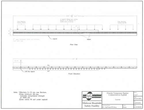
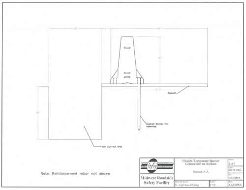
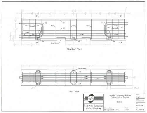
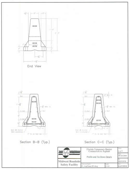
Your request covers two applications of portable F-shape concrete barriers on asphalt pavements. The barrier used was the Kansas F-shape temporary concrete barrier that was developed for bolting through to concrete roadways. The barrier segments were 3.81 m (12.5 ft) long and 813 mm (32 in) tall with three 51 mm (2.0 in) diameter holes cast on each side in the toe of the barrier. Additional steel reinforcement was required around the holes to provide sufficient resistance and containment for the retainer bolts. As seen in the drawings enclosed for reference, adjacent barriers were joined using a pin and loop connection comprised of three sets of rebar loops – two at the top of one barrier meeting one on the top of the other barrier, and vice-versa on the bottom. This detail provided double shear at two locations on each pin, eliminating the need for a retainer bolt at the bottom of the pin.
The first application was placement of the barrier near the edge of an asphalt pavement adjacent to a drop off. To limit deflection and rotation of the barrier 38.1 mm (1. 5 inch) diameter steel pins were inserted through the tie-down holes in the traffic side face of the barrier and driven through the asphalt pavement. Steel plates are welded near the top of the pins to help constrain the barrier upon impact. The system was crash tested on a 51 mm (2 in) thick asphalt pad. The second application was a transition between a free-standing Kansas F-shape temporary barrier on asphalt pavement, and a rigid concrete barrier. The transition used four barrier units and 38.1 mm (1.5 inch) diameter pins. The first unit in the transition had one pin at the down stream end. The second unit had pins installed in the two outside hole locations. The final two units had all three pins installed. All pins were installed in the traffic side face of the barrier. In addition, nested 12 ga thrie beam was bolted across both sides of the barrier at the joint between the pinned barriers and the rigid barrier to reduce the potential for vehicle snagging at the joint.
Crash Testing
One NCHRP Test 3-11 using the 2000P vehicle was conducted on each application. The test data summary sheets are enclosed for reference. The FTB-1 was the test of the tie-down design, and FTB-2 was the test of the transition. In test FTB-1 the asphalt pavement fractured when the barrier was struck, leading to a maximum dynamic deflection of 554 mm (21.8 in) and a permanent set of 283 mm (11.1 in).
In test FTB-2 the impact point was evaluated using finite element analysis, and it was determined that the critical impact point was just upstream of the joint between the first two pinned barriers (the first having one pin in the downstream hole only, and the second barrier having pins at the two ends.) Because of the known stiffness of the next two barriers anchored with three pins, it was determined that the connection between the last two pinned barriers and the rigid concrete barrier would not require a separate crash test. Upon impact the vehicle was redirected with the right rear tire and the pickup truck box landing on the top of the barrier on the traffic side before exiting the system. The maximum permanent set and dynamic barrier deflections were measured to be 133 mm (5.25 in) and 467 mm (18.375 in), respectively.
Results of FTB-1 and FTB-2 met the test and evaluation criteria in NCHRP Report 350 for Test 3-11.
Findings
You asked for acceptance of both the tie-down system for F-shape temporary concrete barriers on asphalt pavements and the approach transition between free-standing temporary concrete barriers and rigid concrete barrier. The tie-down system for F-shape temporary concrete barriers on asphalt pavements was tested with the back face of the barriers positioned 0.15 m (6 in) from the edge of a vertical drop-off in order to represent a worst case impact scenario. You also requested that the tie-down system be accepted for both installations adjacent to a drop-off as tested and installations on standard asphalt paved surfaces. This request is based on the successful results from the dynamic component testing, computer simulation modeling of the barrier system, and full-scale vehicle crash testing of both the tie-down and approach transition designs. We concur in these requests.
The tie-down system for temporary concrete barrier on asphalt and transition system for temporary concrete barrier on asphalt described above and detailed in the enclosed drawings are acceptable for use on the NHS under the range of conditions tested, when such use is acceptable to a highway agency.
In your original letter requesting acceptance MwRSF also noted some specific recommendations for the tie-down and transition regarding the use of the system near a drop-off. You also made a recommendation regarding the use of the tie-down and transition with other barrier designs. We concur that these recommendations should be included in the letter.
"It should also be noted that the tie-down and transition systems described herein were designed for use with the Kansas F-shape temporary concrete barrier system, and therefore, they should not be used with other temporary barrier systems or joint connections without further study. Although it is very likely that this tie-down system can be adapted to other approved temporary barrier systems, it is necessary to utilize some criteria to aid in that determination. They are as follows:
Please note the following standard provisions that apply to the FHWA letters of acceptance:
Sincerely yours,
David A. Nicol, P.E. |
 | ||||||||||||||||||||||||||||||||||||||||||||||||||||||||||||||||||||||||||||||||||||||||||||||||||||||||||||
|---|---|---|---|---|---|---|---|---|---|---|---|---|---|---|---|---|---|---|---|---|---|---|---|---|---|---|---|---|---|---|---|---|---|---|---|---|---|---|---|---|---|---|---|---|---|---|---|---|---|---|---|---|---|---|---|---|---|---|---|---|---|---|---|---|---|---|---|---|---|---|---|---|---|---|---|---|---|---|---|---|---|---|---|---|---|---|---|---|---|---|---|---|---|---|---|---|---|---|---|---|---|---|---|---|---|---|---|---|
|
|
|||||||||||||||||||||||||||||||||||||||||||||||||||||||||||||||||||||||||||||||||||||||||||||||||||||||||||
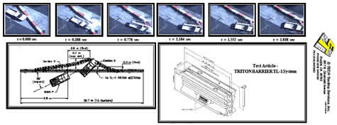
Figure 1. Summary of Results - TRITON BARRIER TL-1 Test -1-4318-001