U.S. Department of Transportation
Federal Highway Administration
1200 New Jersey Avenue, SE
Washington, DC 20590
202-366-4000
| < Previous | Table of Contents | Next > |
When an intersecting roadway is located within a curve, it presents a unique safety challenge. NCHRP Report 600 Human Factors Guidelines for Road Systems points out that the demands on drivers approaching and navigating horizontal curves include visual demands, vehicle control demands, and speed selection. The closer a driver is to the curve, the harder it is for the driver to effectively assimilate information relating to anything other than navigating the curve. The geometry often limits the available sight distance for safe maneuvering and the physical constraints of the intersecting roadway often limit the application of signing and other delineation. Figure 59 shows an example of an intersection within a curve.
The AASHTO Policy on Geometric Design of Highways and Streets recommends that "the alignment should be as straight and the gradient as flat as practical" at intersections to allow for easy recognition of the potential conflicts. It further states that "an intersection on a sharp curve should be avoided or designed to compensate for potential adverse grade and reduced sight distance." However, many agencies have existing intersections with less than ideal design.
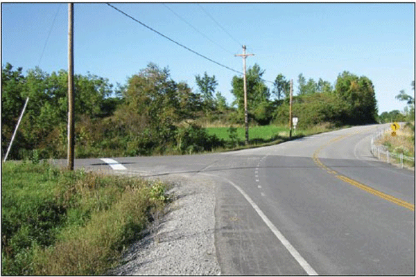
Figure 59. Photo. Dotted edge line extensions at an intersection within a curve.
A study by Indiana Department of Transportation (INDOT) found that curvature was a significant factor in the relative safety of intersections where the major road is a four-lane divided highway. The same study stated that full curvature and superelevation increased crashes by 30 percent in comparison to tangent intersections (Savolainen and Tarko, 2004).
This chapter discusses treatments unique to the combination of intersections and curves as well as modifications that may be appropriate to options discussed in previous chapters to address this situation. Similar to Chapter 5, the cost of some of these countermeasures may be less expensive if the work is completed as part of larger scheduled projects, such as reconstruction or resurfacing, rather than as independent safety projects.
Where an intersecting roadway is within the curve, the traditional means of delineating the roadway alignment is often interrupted. Center line and edge line markings are typically not continued through the intersection. The edge line marking is of particular concern if the intersecting roadway has a wide throat. The MUTCD allows dotted edge line extensions consisting of 2-foot line segments and 2- to 6-foot gaps through intersections along the mainline, as illustrated in Figure 60. In fact, the MUTCD guidance recommends this treatment to help guide motorists through the intersection. As discussed in Chapter 3, providing center line or edge line markings on the approach and through the curve in corridors where markings are otherwise not present channelizes vehicles through the curve. This is particularly beneficial when an intersecting roadway is present within the curve.
Similarly, where chevrons or delineators would typically be used to provide delineation, the discontinuance through the intersection may leave a significant portion of the curve lacking delineation. Adjusting the location of the remaining chevrons or delineators may be appropriate to delineate the maximum curve length. A combination of a curve sign and intersection sign can also be used, which is discussed in Chapter 4. Providing a visible stop line on the minor road approach may also be helpful, especially where the stop line can be seen from a significant distance from the intersection or where crashes indicate stop sign violations.
A combination of treatments used at intersections that are particularly beneficial where there is curvature on either the major or minor road has been dubbed "smooth lane narrowing." As seen in Figure 60, the treatment narrows the lane width approaching the intersection with a combination of markings and rumble strips. The narrowing is accomplished by gradually tapering out from the center. The rumble strips are milled in along both the left and right sides of each direction of travel, with longitudinal center and edge line markings added. The combination of rumble strips and markings to narrow the lanes reduces operating speeds on the intersection approach. When a curve is present, the preferred design is to narrow the lanes on the approach to the curve. The paved width is not changed in this countermeasure, but the narrower lane width continues throughout the entire length of the curve. The rumble strips and markings are discontinued at the intersection, as seen in Figure 61. Using smooth lane narrowing on intersection approaches has been found to reduce all crashes by 32 percent and fatal and injury crashes by 34 percent. Additionally, 85th percentile speeds were reduced by roughly 5 mph. More information on the design of smooth lane narrowing can be found in Crash Impacts of Smooth Lane Narrowing with Rumble Strips at Two-Lane Rural Stop Controlled Intersections.
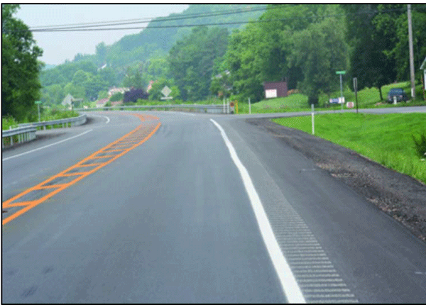
Figure 60. Photo. Pavement markings narrow the travel lane as the driver approaches the intersection.
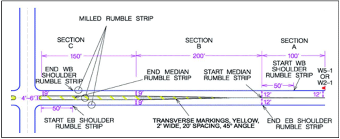
Figure 61. Illustration. Smooth lane narrowing typical design.
Intersections often pose challenges to drivers who do not always see traffic approaching. If there is horizontal or vertical curvature near the intersection, this increases the difficulty. Standard intersection practices may need to be adjusted when there are alignment changes, and treatments that improve intersection visibility may prove even more beneficial at curves with intersections.
A visual trap occurs when the road curves, but visual cues such as breaks in the tree line or the continuation of power poles lead a driver to think the road continues straight. An example of this is illustrated in Figure 62. Frequently, a roadway that intersects the curve is one of the visual miscues. In such cases, additional emphasis should be placed on warning the driver and delineating the curve to overcome the driver expectation of a tangent roadway. Delineators, chevrons, or pavement marking signs are treatments appropriate to address this issue. Also, advanced markings within the lane may be appropriate. See Chapter 3 and 4 for additional information on use of these treatments.
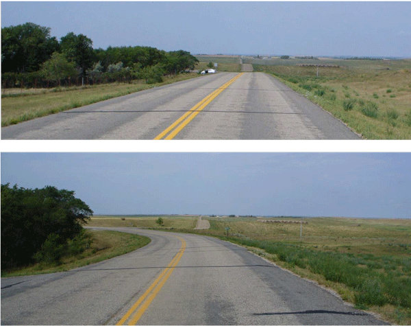
Figure 62. Photo. An example of a visual trap exists when a crest vertical curve blocks the view of the upcoming horizontal curve (top photo). What appears to be a continuation of the road in the distance is actually an intersecting roadway in the midst of a curve (bottom photo).
In the typical rural curve with an intersection, the minor road will be stop-controlled. Assuming the intersecting roadway is aligned perpendicular to the curve of the main roadway and is at or near the center of the curve, the sight distance issues on the outside of curve are similar or perhaps even better than for a tangent roadway section. Providing appropriate sight triangles will often be adequate. The intersection on the inside of the curve, however, is restricted by the geometry and requires the driver to have more mobility to see over-the-shoulder to view oncoming traffic, as seen in Figure 63. If the intersection is not near the center of the curve, sight triangles may cut across the curve and require significantly more clearing, as illustrated in Figure 64. If the terrain is not flat, it may be necessary to cut into slopes to provide the adequate minimum intersection sight distance. The use of and location of guardrails on grades should also be considered as it could interrupt the sight lines for intersections in and near curves.

Figure 63. Photo. Sight distance is limited due to the intersection being inside the curve.

Figure 64. Illustration. Limiting the growth of vegetation is important to maintain appropriate sight triangles.
Where providing the appropriate intersection sight distance is not feasible, the intersection may need to be re-configured. In certain limited cases, an "All-Way" stop-controlled intersection may be appropriate. Careful consideration to speeds and traffic volumes are appropriate before making the decision to change the intersection to an "All-Way STOP." Typically a roundabout would be preferred to this type of control.
Another option for an intersecting roadway with limited sight distance is a dynamic warning sign as shown in Figure 65. The ICWS can be designed to either detect vehicles on the minor road and indicate their presence to drivers on the main road, or indicate to the driver on the minor road when there is oncoming traffic on the mainline. The CMF Clearinghouse lists a 32-percent reduction for all crash types when installing a "Vehicles Entering When Flashing" system (advanced post-mounted signs on the major road and detection loops on the minor road) at stop-controlled intersections (CMF is 4 stars) (Simpson and Troy, 2013). This CMF applies to intersection-related crashes, but does not explicitly consider intersections located along horizontal curves.
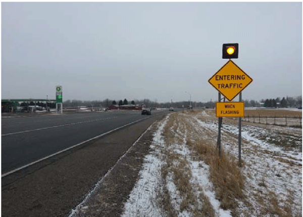
Figure 65. Photo. A dynamic warning sign alerts drivers in real time of other users in the roadway.
The presence of lighting has been shown in improve safety at intersections. The INDOT study of intersections with curvature found that crashes tended to be overrepresented during nighttime conditions (Savolainen and Tarko, 2004). The effect of lighting is generally limited to nighttime crashes, since lighting does not generally improve daytime visibility. The CMF Clearinghouse indicates that the presence of intersection lighting is associated with an 11.9-percent reduction in total nighttime crashes (CMF is 3 stars) (Donnell et al., 2010). The presence of fixed illumination is associated with a 2-percent increase in total daytime crashes on rural roadways (CMF is 2 stars) (Bullough et al., 2012), presumably due to the presence of fixed objects near the intersection.
HFST are particularly beneficial at horizontal curves with an intersection. The treatment, which is described in detail in Chapter 5, may need to be extended depending on the location of the intersection within the curve. In addition, it may be appropriate to extend the treatment to the minor road if it has a high speed approach or crashes indicate a need.
When an intersecting roadway is within the curve, adjustments need to be made to superelevation. This is different than the corrections to superelevation that was discussed in Chapter 5. State design manuals often provide guidance on how to accomplish this, such as the example in Figure 66 provided by Illinois DOT.
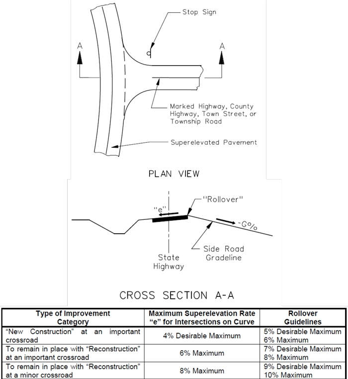
Figure 66. Illustration. Excerpt showing the design of superelevation from Figure 36-1.E of Illinois DOT's Bureau of Design & Environmental Manual. Source: Illinois DOT.
When the road intersecting the curve is unpaved, the result is often either a drop-off at the edge of the pavement or aggregate from the unpaved road gets on the paved portion of the curve. When there is a drop-off, the resulting issue is described in Chapter 4. Loose aggregate on the paved portion of the roadway can result in reduced friction between vehicle tires and the pavement. A solution that can be used for both of these issues is to pave a portion of the approach on the leg of the intersection that is unpaved, as illustrated in Figures 67 and 68.
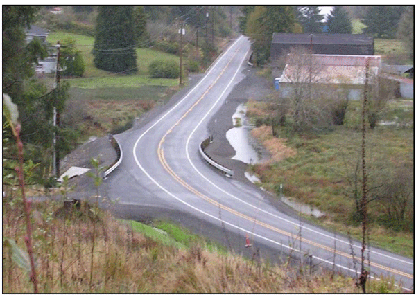
Figure 67. Photo. Intersection with paved approach.
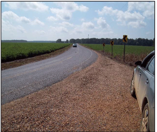
Figure 68. Photo. Intersection with aggregate scattered on paved roadway.
When an intersection is at or near a horizontal curve, it is not uncommon for the location or the configuration of the intersection to cause safety concerns. The issue may be traffic on the major road not seeing or recognizing that a vehicle ahead is stopped while waiting to turn. Or, drivers on either the major or minor road may have difficulty seeing each other due to the alignment, as shown in Figure 69. Low-cost solutions cannot always address these stated intersection sight distance concerns. When considering higher cost solutions, it is important to address the most severe and more frequent crash types.

Figure 69. Illustration. Intersection with a skewed approach with an arrow indicating the driver's line of sight.
Roundabouts are one of the most efficient ways to reconfigure an intersection, particularly when there is existing curvature. A roundabout is a circular intersection with yield control for all legs approaching the intersection. As illustrated in Figure 70, roundabouts typically provide the most efficient flow of traffic, reduce severe crashes, and can often be built at the same or lower cost than the more traditional options discussed below.
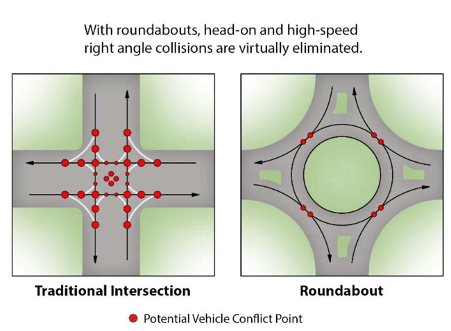
Figure 70. Illustration. Comparison of potential conflict points between a traditional intersection and roundabout.
Roundabouts use roadway curvature and islands to reduce speeds of approaching vehicles. Most importantly, roundabouts reduce the points of conflict. Drivers need only check for traffic on their left before entering the circulating roadway. Crash types within a roundabout tend to be sideswipe and rear-end, which are typically less severe than the angle crashes that are more common at a traditional intersection. Severity is also typically reduced because speeds are slower at a roundabout. Traffic flow is smooth because each approaching vehicle only waits if there is a not an opening in within the circular portion of the roadway.
Where a skewed intersection currently exists–which is common within horizontal curves–redesigning the intersection with a roundabout allows more flexibility in alignment than the standard practice of realigning the minor roadway to make the intersection perpendicular (shown in Figures 71, 72, and 73). In addition, the roundabout will typically result in significantly greater crash reductions because all turning movements at the intersection are safer due to the reduced speeds and conflict points. The HSM states that by converting from a two-way stop control mechanism to a roundabout, a location can experience an 82-percent reduction in severe (injury/fatal) crashes and a 44-percent reduction in overall crashes. It also indicates that by converting a signalized intersection to a roundabout, a location can experience a 78-percent reduction in severe (injury/fatal) crashes and a 48-percent reduction in overall crashes (AASHTO, 2010).
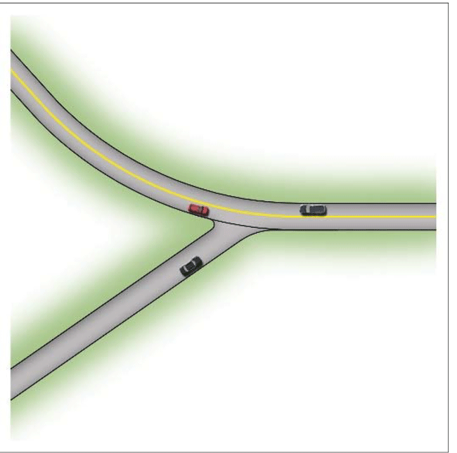
Figure 71. Illustration. Typical skewed intersection within a curve.
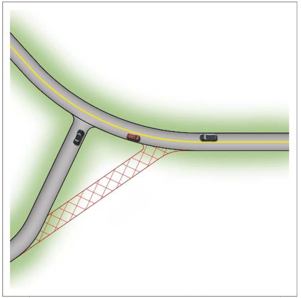
Figure 72. Illustration. Re-aligning a skewed intersection to provide a perpendicular intersection.
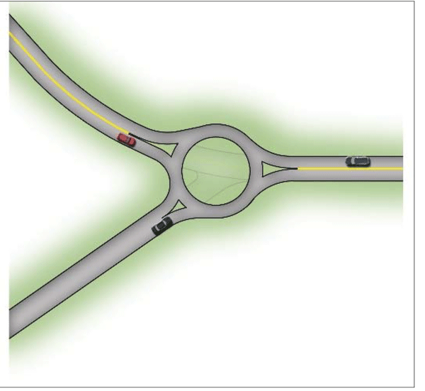
Figure 73. Illustration. Reconfiguring the intersection with a roundabout.
If turning movements at the intersection within a horizontal curve are the primary safety concern and a roundabout is not feasible to resolve the issue, adding turn lane for the primary turning movement may resolve the problem. Left turn lanes on the major roadway remove turning vehicles from the high-speed through lane. If existing widths allows room to change the lane configuration with little or no additional pavement widening, restriping to add turn lanes can be very cost effective. The CMF Clearinghouse indicates that providing a channelized left-turn lane at a three-leg intersection on the major-road approach is associated with a 27-percent reduction in all crashes (CMF is 3 stars) (Elvik and Vaa, 2004). The CMF Clearinghouse alsoindicates that providing a right-turn lane on one major approach to a stop-controlled intersection is associated with a 14-percent reduction in all crashes (CMF is 3 stars) (Harwood et al., 2002). While these are not specifically for intersections within curves, it would be expected that intersections within curves would experience the same benefits in safety.
| < Previous | Table of Contents | Next > |
