U.S. Department of Transportation
Federal Highway Administration
1200 New Jersey Avenue, SE
Washington, DC 20590
202-366-4000
This section of the Desk Reference focuses on treatments for highway design elements in six areas to enhance the performance of aging drivers at interchanges. After the last design element, two promising practice treatments are also presented.
Proven Practices
Promising Practices
Assume a minimum specific ratio of 1 inch of letter height per 30 feet of legibility distance for new or reconstructed installations and for sign replacement at interchanges and on their approaches.
It is required by the 2009 MUTCD that mixed-case lettering be used for destination and street names.
The MUTCD recommends Overhead Arrow-per-Lane guide signs to be used on all new or reconstructed freeways and expressways as described in MUTCD Sections 2E.20 and 2E.21, whereby the number of arrow shafts appearing on the sign matches the number of lanes on the roadway at the location of the sign (see Figure 42).
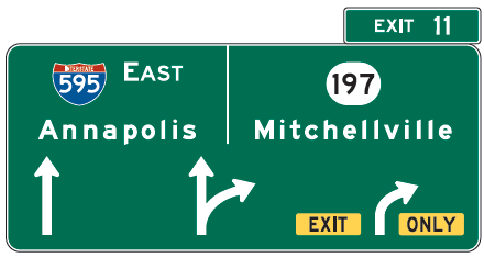
Figure 42. Example overhead arrow-per-lane sign
Freeway and expressway splits or multi-lane exit interchanges that contain an interior option lane in which traffic can either leave the route or remain on the route, or choose either destination at a split, from the same lane should use overhead arrow-per-lane guide signs rather than diagrammatic guide sign designs.
Microprismatic retroreflective sheeting should be used on overhead and ground-mounted guide signs.
The rationale and supporting evidence for these treatments can be found beginning on page 224 of the Handbook.
A 48-in x 30-in guide sign panel with the legend Freeway Entrance (see Figure 43), using a minimum letter height of 8 in, should be consistently used in situations where freeway entrance and exit ramps are adjacent to one another (such as at a partial cloverleaf interchange) and placed as described in Section 2D.46 and shown in Figure 2D-14 of the MUTCD.
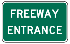
Figure 43. (MUTCD D13-3)
Where adjacent entrance and exit ramps intersect with a crossroad, the use of a median separator, either painted or preferably raised, is recommended, with the nose of the separator delineated with yellow retroreflectorized markings and extending as close to the crossroad as practical without obstructing the turning path of vehicles (see Figure 44). Where engineering judgment determines the need for the median nose to be set back from the intersection, the setback distance should be treated by a 12-in or wider yellow stripe. In addition, a KEEP RIGHT (R4-7) sign should be posted on the median separator nose, if it is raised.
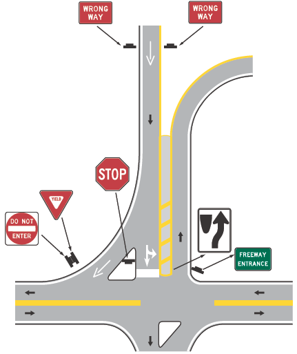
Figure 44. Recommended signs and markings for adjacent entrance/exit ramps at a crossroad intersection
For diagrammatic guide signs depicting lane use for entry to a freeway from an urban multilane arterial, maximum visibility is achieved through overhead sign placement. Where this is not feasible, two advance ground-mounted diagrammatic guide signs should be used, one placed at 0.5 mi and the second placed at 0.25 mi in advance of the interchange (see Figure 45).
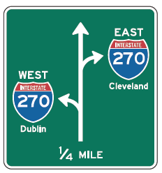
Figure 45. Advance ground-mounted diagrammatic sign
The rationale and supporting evidence for these treatments can be found beginning on page 235 of the Handbook.
Delineation in the vicinity of the exit gore at non-illuminated and partially illuminated interchanges should include, as a minimum, raised pavement markers and retroreflective post-mounted delineators as shown in Figure 46.
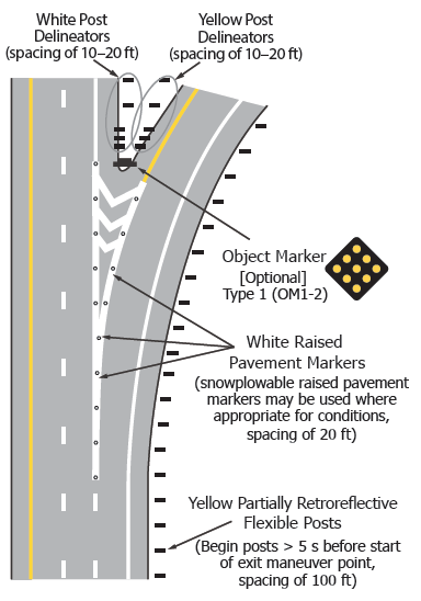
Figure 46. Recommended raised pavement markers and post-mounted delineators at an exit gore
Where engineering judgment has identified a hazardous gore area (e.g., containing a ditch) or other special visibility need, the minimum treatments described above should be supplemented by adding Type 1 object markers to the exit gore sign post as illustrated in Figure 46.
Post-mounted delineators and/or chevrons should be applied to delineate the controlling curvature on exit ramps, as illustrated in Figure 47.
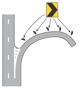
Figure 47. Placement of chevrons on the controlling curve of an exit ramp
The rationale and supporting evidence for these treatments can be found beginning on page 238 of the Handbook.
A parallel (rather than a taper) design for entrance ramp geometry is recommended, as shown in Figure 48. AASHTO recognizes the operational and safety benefits of long acceleration lanes provided by parallel type entrances. A long acceleration lane provides more time for merging drivers to find an opening in the through-traffic stream. A parallel style entrance lane length of at least 1,200 ft, plus a taper, is desirable.
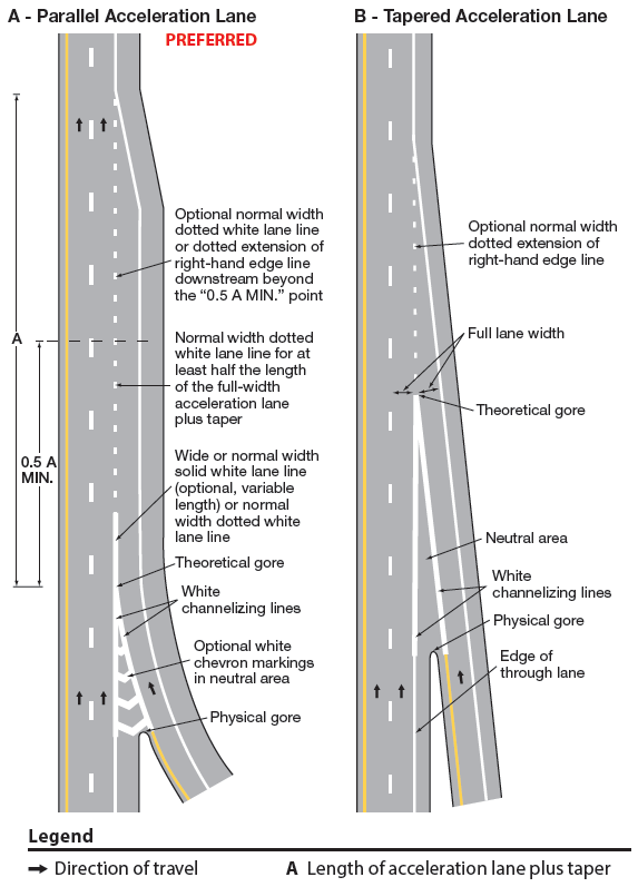
Figure 48. Recommended markings for acceleration lanes from entrance ramps onto freeways
The AASHTO (2011) decision sight distance values (instead of stopping sight distance) should be consistently applied in locating ramp exits downstream from sight-restricting vertical or horizontal curvature on the mainline.
The rationale and supporting evidence for these treatments can be found beginning on page 243 of the Handbook.
Complete interchange lighting (CIL) is the preferred practice, but where a CIL system is not feasible to implement, a partial interchange lighting (PIL) system comprised of two high-mast installations (e.g., 60- to 150-ft-high structures with 3 to 12 luminaires per structure) per ramp is recommended, with one fixture located on the inner ramp curve near the gore, and one fixture located on the outer curve of the ramp, midway through the controlling curvature.
The rationale and supporting evidence for this treatment can be found beginning on page 248 of the Handbook.
To meet overriding concerns for enhanced conspicuity of signing for prohibited movements, the following countermeasures should be used where DO NOT ENTER (R5-1) and WRONG WAY (R5-1a) signs are used:
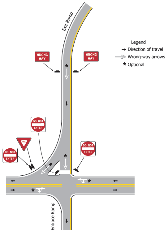
Figure 49. Recommended signing for restricted movements on an exit ramp
The rationale and supporting evidence for these treatments can be found beginning on page 252 of the Handbook.
At major freeway interchanges and route splits, route shield markings should be used in the lanes approaching the split to guide drivers to the correct approach lane (see Figure 50). The placement of this type of marking should be just prior to the location of the advance guide signs.
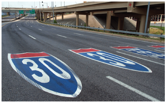
Figure 50. Route shield markings at freeway junctions
The rationale and supporting evidence for these treatments can be found beginning on page 257 of the Handbook.
Additional treatments to counter wrong-way driving by aging drivers (e.g., improved lighting, channelization, signs and markings in addition to those in Treatment 30) should be considered where exit ramps intersect with surface streets. Those treatments include:
The rationale and supporting evidence for these treatments can be found beginning on page 257 of this Handbook.

