FHWA Course on Bicycle and Pedestrian Transportation
Lesson 11
Traffic Calming
11.1 Purpose
Traffic calming is a traffic management approach that evolved in Europe and
is now being implemented in many U.S. cities. The following definition is quoted
from An Illustrated Guide to Traffic Calming by Hass Klau (1990):
"Traffic calming is a term that has emerged in Europe to describe
a full range of methods to slow cars, but not necessarily ban them, as they
move through commercial and residential neighborhoods. The benefit for pedestrians
and bicyclists is that cars now drive at speeds that are safer and more compatible
to walking and bicycling. There is, in fact, a kind of equilibrium among all
of the uses of a street, so no one mode can dominate at the expense of another."
This chapter explores the principle of traffic calming and provides a variety
of studies, design details, and photographs of areas where traffic calming has
been effectively used in the United States and in Europe. Along with the advantages
of traffic calming, the text describes mistakes that practitioners have sometimes
made in implementing traffic-calming techniques.
11.2 Traffic-Calming Objectives
The most fundamental traffic-calming goal is to reduce the speed of vehicular
movement. With reduction of speed, the following objectives can be realized:
- Improved "feel" of the street.
This objective calls for increased community involvement in and "ownership"
of the street. If people feel more comfortable on the street, they are more
likely to walk or bicycle there and to engage in other street-oriented activities
with their neighbors. A key aspect of achieving this objective is reducing
the perceived threat of danger from motor traffic.
- Enhanced aesthetic values and a sense of nature.
Several traffic-calming techniques, such as street landscaping, pedestrian
amenities, and reclamation of roadway areas can serve as community open space.
Not only do these techniques make the neighborhood more attractive, but they
also break up long, uninterrupted street vistas conducive to speeding and
convey the message that "this is a pedestrian place."
- Reduced crime.
It's harder to make a speedy getaway if a fleeing felon has to deal with speed
humps, woonerfs, and traffic circles. It's harder to get away without being
spotted if there are "eyes on the street" - if the street is a positive,
community focus.
- Equitable balance among transportation modes.
With reduced motorist speeds, safety is improved. Pedestrians and bicyclists
have more time to detect and avoid motor vehicles. Traffic calming sends the
message that "motor vehicles don't exclusively OWN the roadway"
- that other modes have equal rights. Studies that evaluate traffic-calming
improvements show increased levels of walking, bicycling, and transit use
following installation.
- Increased safety/decreased severity of injury in traffic
crashes.
With reduced speeds comes a significant reduction in the number and severity
of crashes involving motor vehicles. Traffic-calming facility evaluations
uniformly show fewer crashes, fewer fatalities, and less severe injuries.
- Improved air quality and noise levels.
Slower moving vehicles make less noise and, generally, emit fewer pollutants.
- Decreased fuel consumption.
With more trips made by walking, bicycling, and transit, and with slower traffic
speeds, fuel consumption reductions of 10 to 12 percent have been reported.
- Continued accommodation of motor vehicle traffic.
An important objective is the continued accommodation of motor vehicle
traffic. Although traffic calming shifts the balance among travel modes, this
shift should not result in severely restricted traffic volumes or in shifting
traffic problems from the traffic-calmed area to other streets.
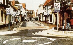
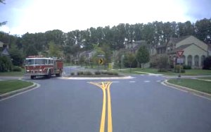
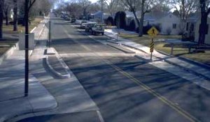
Traffic-calming devices are used to break up long
uninterrupted street vistas that encourage speeding.
11.3 Traffic-Calming Issues
When any new traffic management approach is introduced, issues, concerns, and
questions are bound to arise. Design decisions related to traffic can have far-reaching
consequences. Lives, economic well-being, and urban livability are directly
affected. Professional engineers, planners, government, and the public all are
aware of and sensitive to proposals for changes in the traffic environment.
Roadway congestion, air quality, traffic safety, street crimes, and the high
cost of new improvements are among the most-widely debated issues in America
today. New design ideas are, and should be, subjected to rigorous testing and
evaluation before being accepted as part of the standard engineering and transportation
planning tool kit. Traffic calming is not a panacea for urban transportation
woes, but it can have significant benefits in many situations. In considering
the application of traffic-calming techniques, what specific issues are likely
to arise? The discussion on the following pages focuses on traffic-calming issues.
(Note: Studies and statistics referenced are cited in FHWA Case Study Nos. 19
and 20, National Bicycling and Walking Study.)
- Traffic safety.
The Issue: Encouraging people to walk, play, and bicycle in and next to the
streets is just asking for trouble. They will have a false sense of security
and accidents will increase. They will develop bad habits that may increase
their when they leave the neighborhood. Comment: Traffic-calming measures
have been implemented in many European cities. In the Netherlands and Germany,
extensive research has been conducted to evaluate the safety and impact of
traffic-calming techniques and devices.
- Impact on traffic volumes, distribution, and operations.
The Issue: Traffic calming will never work on anything except very low-volume
residential streets. It will substantially reduce the amount of traffic that
a street can handle efficiently and this is counterproductive. We need to
move vehicles, not restrict them. Furthermore, if we slow traffic on one street,
the traffic will simply be diverted to another street. The net result will
be increased congestion and more problems overall. Comment: A 5-year German
Federal Government evaluation of traffic calming and follow-up research found:
- Little change in overall traffic volumes.
- Reduction in average vehicle speeds by almost 50 percent.
- Average increase in motorist trip time of only 33 seconds.
-
Lack of proven design standards.
The Issue: There are no uniform, accepted, and legally defensible standards
to follow. If we want to try traffic calming, where can we get specific information
about design? Comment: Many U.S. cities are now developing and testing design
guidelines for traffic-calming improvements. Although uniform, national standards
have yet to evolve, valuable experience is being gained. The list of references
at the end of this lesson provides a starting point for further exploration
of specific design approaches.
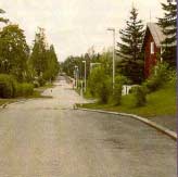
Traffic calming can be termed as engineering and other physical measures
designed to control traffic speeds and encourage driving behavior
appropriate to the
- Liability.
The Issue: These traffic-calming ideas may be accepted in Europe, but they
haven't really been tried here. Are we opening the door to all kinds of legal
problems if somebody crashes on a traffic circle or a speed table and sues
us?
Comment: When considering the use of any new design approach, concerns about
liability can be addressed somewhat through performance of "due diligence"
on the part of the engineer, planner, or other professionals involved in the
design. Research into the experiences of other U.S. cities, European standards,
and evaluation studies should be thorough and followed up with a first-hand
look if possible. Construction of a pilot project or other testing of proposed
designs can benefit, as can ongoing and systematic evaluation of the improvements
once installed.
- Emergency and service vehicle access.
The Issue: Construction of speed bumps, neckdowns, medians, and traffic circles
will increase response times for emergency vehicles and may restrict access
for garbage trucks, delivery vans, and other large vehicles. Comment: Studies
in Berkley and Palo Alto, CA, show that traffic management measures (e.g.,
traffic diverters, bicycle boulevards) have not impaired police or fire emergency
response times.
- The Seattle Engineering Department works closely with its Fire Department
to design and field-test traffic circles on a site-specific basis to ensure
good emergency access.
- Impacts on bicycling.
The Issue: Pavement texturing, speed tables, wider sidewalks, "bulb-outs"
at corners and similar improvements may make things better for pedestrians,
but may have a negative impact on bicycling. Comment: A 5-year German Federal
Government evaluation of traffic calming and follow-up research found doubling
of bicycle use over a 4-year period.
- Implementation of traffic management strategies in the downtown area
of the Dutch City of Groningen contributed to a substantial increase in
bicycling and walking. Bicycle use is now well over 50 percent of all
trips.
- Studies of traffic-calming areas in Japan show increases in both bicycle
and pedestrian traffic volumes along most routes. (Note: Cyclists and
Traffic Calming, a Technical Note publication of the Cyclists Touring
Club (see references, end of lesson),includes extensive information on
adapting traffic-calming techniques for bicycling.
Emergency vehicle access should always be considered when incorporating traffic-calming measures.
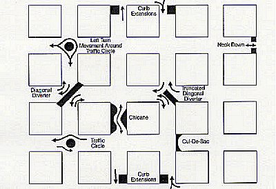
11.4 Traffic-Calming Devices
Traffic calming has many potential applications, especially in residential
neighborhoods and small commercial centers. Traffic-calming devices can be grouped
within the following general categories:
- Bumps, humps, and other raised pavement areas.
- Reducing street area where motor traffic is given priority.
- Street closures.
- Traffic diversion.
- Surface texture and visual devices.
- Parking treatments.
Frequently, a combination of traffic-calming devices is used. Examples of such
combinations will be discussed briefly, including:
- The woonerf.
- Entry treatments across intersections.
- Shared surfaces.
- Bicycle boulevards.
- Slow streets.
- Channelization changes.
- Traffic calming on a major road.
- Modified intersection design.
-
Bumps, humps, and other raised pavement areas. This category
includes all traffic-calming devices raised above pavement level. Drivers
must slow down when they cross these devises or suffer an uncomfortable KER-BUMP
or (KER-BUMP-KER-BUMP), running the risk of spilled coffee and a severe jolt
to their tailbones. Although people often gripe about the inconvenience of
having to slow down for these devices, they don't have much choice. Their
effectiveness at slowing traffic cannot be disputed. They are sometimes referred
to as "Silent Policemen."
Included in this category are:
- Speed bumps.
- Speed humps.
- Raised crosswalks.
- Raised intersections.
The following are brief descriptions of each, with definitions, comments,
and examples:
Speed Bumps
A speed bump is a raised area in the roadway pavement surface extending transversely
across the travel way, generally with a height of 3 to 6 inches and a length
of 1 to 3 feet.
Design Considerations:
- Most effective if used in a series at 300- to 500- foot spacing.
- Typically used on private property for speed control - parking lots,
apartment complexes, private streets, and driveways.
- Speed bumps are not conducive to bicycle travel, so they should be
used carefully
Speed bumps can be combined with curb extensionsand a winding
street alignment. Signing and pavement markings should clearly identify the bump.
Speed Humps
A speed hump (or "road hump") is a raised area in the roadway pavement
surface extending transversely across the roadway. Speed humps normally have
a minimum height of 3 to 4 inches and a travel length of approximately 12
feet, although these dimensions may vary. In some cases, the speed hump may
raise the roadway surface to the height of the adjacent curb for a short distance.
The humps can be round or flattopped. The flat-topped configuration is sometimes
called a "speed table." Humps can either extend the full width of
the road, curb-to-curb, or be cut back at the sides to allow bicycles to pass
and facilitate drainage.
Design Considerations:
- If mid-block pedestrian crossings exist or are planned, they can be
coordinated with speed hump installation since vehicle speeds will be
lowest at the hump to negotiate ramps or curbs between the sidewalk and
the street.
- The hump must be visible at night.
- Speed humps should be located to avoid conflict with underground utility
access to boxes, vaults, and sewers.
- Speed humps should not be constructed at driveway locations.
- Speed humps may be constructed on streets without curbs, but steps should
be taken to prevent circumnavigation around the humps in these situations.
- Adequate signing and marking of each speed hump is essential to warn
roadway users of the hump's presence and guide their subsequent movements.
- Speed humps should not be installed in street sections where transit
vehicles must transition between the travel lane and curbside stop. To
the extent possible, speed humps should be located to ensure that transit
vehicles can traverse the hump perpendicularly.
A single hump acts as only a point speed control. To reduce speeds along
an extended section of street, a series of humps is usually needed. Typically,
speed humps are spaced at between 300 and 600 feet apart.
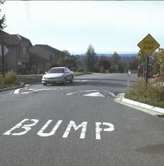
Speed humps slow traffic speeds on residential streets.
Example:
Bellevue, Washington has installed speed humps in residential neighborhoods
(labeled as speed "bumps" below, although broader than the typical
speed bump). The City uses a 12-foot-wide hump, 3 inches high at the center.
The design allows for little or no discomfort at speeds of 15 to 25 mph,
but will cause discomfort at higher speeds. The humps are marked clearly,
distinguishing them from crosswalks. White reflectors enhance nighttime
visibility.
Bellevue found that the speed humps reduced traffic speeds and volumes.
The humps, in general, received strong public support, and residents favored
their permanent installation.
The following concerns were raised regarding the speed hump installation:
- Concern about restricted access and increased response time for emergency
vehicles. The Bellevue Fire Department asked that the humps be installed
on primary emergency access routes.
- Concern about aesthetics of signing and markings at the traffic humps.
Residents raising the concerns, however, felt that the speed reductions
compensated for the appearance of the humps.
Concern about the effectiveness of the humps in reducing motor vehicle speeds
along the length of a street, not at just two or three points. The distance
between speed humps was found to have an impact on traffic speeds. The City
found that maximum spacing should be approximately 500 feet.
The Bellevue Department of Public Works concluded that speed humps were effective
speed-control measures on residential streets and recommended their use be
continued. The table on the following page summarizes "before" and
"after" data related to the Bellevue speed humps:
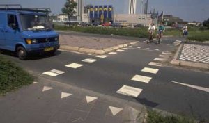
Raised Crosswalks
Raised crosswalks are essentially broad, flat-topped speed humps that coincide
with pedestrian crosswalks at street intersections. The crosswalks are raised
above the level of the roadway to slow traffic, enhance crosswalk visibility,
and make the crossing easier for pedestrians who may have difficulty stepping
up and down curbs.
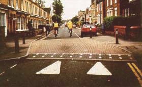
Raised crosswalks can both slow motor traffic and give pedestrians a
continuouslevel surface at the crossing. Changes in texture
and color help define the edges of the crossing.
Table 2. Bellevue Speed Humps Findings
| Location |
Street Type/Width |
# of Humps |
Hump Spacing |
Speed Limit |
Before |
After |
| 85th % speed |
VPD |
85th % speed |
VPD |
| Somerser Drive SE |
Two-way, 40 feet wide local residential neighborhood street |
2 |
340' |
25 mph |
39 mph |
795 |
27 mph |
541 (VPD increased to 746 when the hump was reduced from
3/4" to 3") |
| Highland Drive SE |
Two-way, 35 feet wide neighborhood collector |
3 |
220' |
25 mph |
36 mph |
1,700 |
25 mph |
No change because no alternative route exists. |
| 166th/162nd Avenue SE |
Two-way, 36 feet wide local residential street; walk to school route |
2
2 |
600'
580' |
25 mph
25 mph |
37 mph
37 mph |
655
472 |
24 mph
27 mph |
0.17
0.17 |
| SE 63rd Street |
Two-way, 35 feet wide local residential street temporarily serving as
a connection between two minor arterials |
2
3 |
1,000'
500' |
25 mph |
36 mph |
2,456 |
27 mph |
2,802 |
| Yarrow Bay neighborhood |
Primarily a neighborhood connector |
2 |
400' |
|
39 mph |
3,685
1,641 |
25 mph |
2,931
1,653 |
Source: FHWA Case Study No. 19.
 |
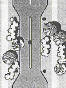 |
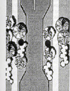
| ONE-LANE SLOW POINT |
TWO-LANE SLOW POINT |
Design Considerations:
- Can be constructed of brick, concrete block, colored asphalt or cement,
with ramps striped for better visibility.
- Raised crosswalks are applicable:
- On roadways with vehicular speeds perceived as being incompatible
with the adjacent residential land uses.
- Where there is a significant number of pedestrian crossings.
- In conjunction with other traffic-calming devices, particularly entry
treatments.
- On two-lane or fewer residential streets classified as either "local
streets" or neighborhood collector streets."
- On roadways with 85th percentile speeds less than 45 mph.
Intersection Humps/Raised Intersections
Intersection humps raise the roadway at the intersection, forming a type of
"plateau" across the intersection, with a ramp on each approach. The
plateau is at curb level and can be enhanced through the use of distinctive
surfacing such as pavement coloring, brickwork, or other pavements. In some
cases, the distinction between roadway and sidewalk surfaces is blurred. If
this is done, physical obstructions such as bollards or planters should be considered,
restricting the area to which motor vehicles have access.
Design Considerations:
- Ramps should not exceed a maximum gradient of 16 percent.
- Raised and/or textured surfaces can be used to alert drivers to the need
for particular care.
- Distinctive surfacing helps reinforce the concept of a "calmed"
area and thus plays a part in reducing vehicle speeds.
- Distinctive surfacing materials should be skid-resistant, particularly
on inclines.
- Ramps should be clearly marked to enable bicyclists to identify and anticipate
them, particularly under conditions of poor visibility.
- Care must be taken so the visually impaired have adequate cues to identify
the roadway's location (e.g., tactile strips). Color contrasts will aid
those who are partially sighted.
- Reducing street area where motor traffic is given priority.
This category of traffic-calming techniques includes all those that reduce
the area of the street designated exclusively for motor vehicle travel. "Reclaimed"
space is typically used for landscaping, pedestrian amenities, and parking.
Discussed here are:
- Slow points.
- Medians.
- Curb extensions.
- Corner radius treatment.
- Narrow traffic lanes.

This traffic-calming measure uses a landscaped median to narrow the
travel lanes.
Slow Points (neck-downs, traffic throttles, pinch points)
Slow points narrow a two-way road over a short distance, forcing motorists
to slow and, in some cases, to merge into a single lane. Sometimes these are
used in conjunction with a speed table and coincident with a pedestrian crossing.
The following are advantages and disadvantages of both one-lane and two-lane
slow points:
(1) One-lane slow point.
One-lane slow points restrict traffic flow to one lane. This lane must accommodate
motor traffic in both travel directions. Passage through the slow point can
be either straight through or angled.
Advantages:
- Vehicle speed reduced.
- Most effective when used in a series.
- Imposes minimal inconvenience to local traffic.
- Pedestrians have a reduced crossing distance, greater safety.
Disadvantages:
- Reduced sight distances if landscaping is not low and trimmed.
- Contrary to driver expectations of unobstructed flow.
- Can be hazardous for drivers and bicyclists if not designed and maintained
properly.
- Opposing drivers arriving simultaneously can create confrontation.
(2) Two-lane slow point.
Two-lane slow points narrow the roadway while providing one travel lane in
each direction.
Advantages:
- Only a minor inconvenience to drivers.
- Regulates parking and protects parked vehicles as the narrowing can
help stop illegal parking.
- Pedestrian crossing distances reduced.
- Space for landscaping provided.
Disadvantages:
- Not very effective in slowing vehicles or diverting through traffic.
- Only partially effective as a visual obstruction.
Design Considerations:
- Where slow points have been used in isolation as speed control measures,
bicyclists have felt squeezed as motorists attempt to overtake them at
the narrowing. Not all bicyclists have the confidence to position themselves
in the middle of the road to prevent overtaking on the approach to and
passage through the narrow area.
- To reduce the risk of bicyclists' being squeezed, slow points should
generally be used in conjunction with other speed control devices such
as speed tables at the narrowing. Slower moving drivers will be more inclined
to allow bicyclists through before trying to pass. Where bicycle flows
are high, consideration should be given to a separate right-of-way for
bicyclists past the narrow area.
- A textured surface such as brick or pavers may be used to emphasize
pedestrian crossing movement. Substituting this for the normal roadway
surface material may also help to impress upon motorists that lower speeds
are intended.
- Such measures should not confuse pedestrians with respect to the boundary
of the roadway area over which due care should still be taken. In particular,
where a road is raised to the level of the adjacent sidewalk, this can
cause problems for those with poor sight. However, a tactile strip may
help blind people in distinguishing between the roadway and the sidewalk;
similarly, a color variation will aid those who are partially sighted.
- Slow points can be used to discourage use of the street by large vehicles.
They can, however, be barriers to fire trucks and other emergency vehicles.
Some designs permit access by emergency vehicles by means of lockable
posts or ramped islands.
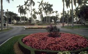
- Slow points can enhance the appearance of the street. For example,
landscaped islands can be installed, intruding into the roadway to form
a narrow "gate" through which drivers must pass. Landscaping
enhances the neighborhood's sense of nature and provides a visual break
in views along the street.
- Slow points are generally only sanctioned where traffic flows are less
then 4,000 to 5,000 vehicles per day. Above this level, considerable delays
will occur during peak periods.
- Clear signing should indicate traffic flow priorities.
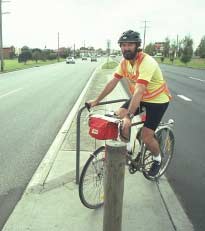
This median provides a diagonal waiting area for bicyclists,
including a railing to hold onto.
Slow Point Examples:
Medians
Medians are islands located along the roadway centerline, separating opposing
directions of traffic movement. They can be either raised or flush with the
level of the roadway surface. They can be expressed as painted pavement markings,
raised concrete platforms, landscaped areas, or any of a variety of other
design forms. Medians can provide special facilities to accommodate pedestrians
and bicyclists, especially at crossings of major roadways.
Design Considerations:
- Medians are most valuable on major, multi-lane roads that present safety
problems for bicyclists and pedestrians wishing to cross. The minimum
central refuge width for safe use by those with wheelchairs, bicycles,
baby buggies, etc. is 1.6 meters (2 meters is desirable).
- Where medians are used as pedestrian and bicyclist refuges, internally
illuminated bollards are suggested on the medians to facilitate quick
and easy identification.
- Used in isolation, roadway medians do not have a significant impact
in reducing vehicle speeds. For the purpose of slowing traffic, medians
are generally used in conjunction with other devices, such as curb extensions
or roadway lane narrowing.
Several caveats apply:
- To achieve meaningful speed reductions, the travel lane width reduction
must be substantial and visually obvious. The slowing, however, is temporary;
as soon as the roadway widens again, traffic resumes its normal speed.
- Bicyclists have been put at risk of being squeezed where insufficient
room has been left between a central median and the adjacent curb. Experience
shows that most drivers are unlikely to hold back in such instances to
let bicyclists go through first. This threat is particularly serious on
roads with high proportions of heavy vehicles.
- The contradiction between the need to reduce the roadway width sufficiently
to lower motorist speeds, while at the same time leaving enough room for
bicyclists to ride safely, must be addressed. This may be achieved by
reducing the roadway width to the minimum necessary for a bicyclist and
a motorist to pass safely (i.e., 3.5 meters).
There are three suggestions:
- Introducing color or texture changes to the road surface material around
the refuge area reminds motorist that a speed reduction is intended.
- White striping gives a visual impression that vehicles are confined
to a narrower roadway than that created by the physical obstruction -
adjacent areas exist that vehicles can run over, but these are not generally
apparent to approaching drivers.
- In some cases, provide an alternate, cut-through route for the bicyclists.
A 7-foot radius allows for a slow and safe turn. As the radius increases,
so does the speed of the vehicle.
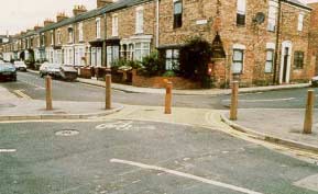
Curb Extensions
The sidewalk and/or landscaped area on one or both sides of the road is extended
to reduce the roadway to a single lane or minimum-width double lane. By reducing
crossing distances, sidewalk widening is used to facilitate easier and safer
pedestrian movement.
Reducing roadway width results in vehicle speed reductions. When curb extensions
are used at intersections, the resultant tightened radii ensure that vehicles
negotiating the intersection do so at slow speeds.
Design Considerations:
- Can be installed either at intersections or midblock.
- May be used in conjunction with other trafficcalming devices.
- Curb extensions are limited only to the degree that they extend into
the travelway. Curb extensions cannot impede or restrict the operation
of the roadway.
- Successful bicycle facilities need a clear separation from sidewalk
and street pavement, with adequate distances from parked cars to avoid
opening doors. Cross-traffic should be slowed to allow bicyclists better
continuity and safety.
- Narrowing certain streets can, at the same time, create safer bicycle
facilities, but care should be taken that bicyclists are not squeezed
by overtaking vehicles where the road narrows. Encouraging motorists to
let the bicyclists through first by using complementary trafficcalming
techniques such as speed tables and cautionary signing or leaving sufficient
room for both to pass safely at the narrowing would be appropriate measures.
- If it is expected that a motorist should be able to pass a bicyclist,
the minimum desirable width is 3.5 meters.
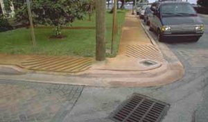
Curb extensions can be employed to facilitate bicycle movement where a segregated
multi-use trail crosses a busy street.
Corner Radius Treatment
Corner radii of intersection curbs are reduced, forcing turning vehicles to
slow down. Efforts to accommodate trucks and other large vehicles have historically
led to increased corner radii at intersections.
The following results have been observed:
- Large vehicles (trucks, vans, etc.) turn the corners easily.
- Other vehicles turn faster than with a reduced radius corner.
- Pedestrian crossing distances are increased by up to 4 feet, depending
on the radius.
- Pedestrian safety is decreased, due to higher speeds.
- The sharper turns that result from the reduced radii require motorists
to reduce speed, increasing the time available to detect and take appropriate
actions related to pedestrians at the crossing.
The design of street closures should provide specific parking areas to
discourage obstruction of bicycle and pedestrian traffic.
Advantage:
- Can result in increased safety for pedestrians by reducing crossing distances
and slowing the speed of turning vehicles.
Disadvantages:
- May result in wide swings in turning movements of large vehicles.
- May affect response times for emergency vehicles.
Design Consideration:
- To slow traffic, a corner radius of approximately 7 feet is recommended.
Narrow Traffic Lanes
Especially in residential areas, wide streets may not be necessary or desirable.
Wide traffic lanes encourage faster motor vehicle speeds. Consideration should
be given to the review of cross-sections for all street classifications to determine
whether roadway lane widths can be reduced (within AASHTO guidelines) so more
area can be dedicated to bicycle and pedestrian use and associated trafficcalming
facilities.
Advantage:
- Additional area for landscaping, and pedestrian facilities.
- Reduced vehicle speeds and increased safety.
Disadvantages:
- On-street parking may be restricted.
Design Consideration:
- Cross-section approaching the reduced-width street should also be slowed.
Example: City of Portland, Skinny Street Program
The City of Portland requires most newly constructed residential streets to
be 20 or 26 feet wide, depending on neighborhood on-street parking needs. In
the past, residential streets were required to be as wide as 32 feet. To achieve
a variety of benefits, the City reduced residential street widths. The City's
Fire Bureau participated in the development of this standard to ensure access
for emergency vehicles.
- Street closures.
Three types of street closures are described in the following discussion:
- Complete street closures.
- Partial street closures.
- Driveway links. (Caution: Street closures must be considered in an area-wide
context or traffic problems may simply shift to another nearby street).
Complete Street Closures
Street closures, generally on residential streets, can prohibit through-traffic
movement or prevent undesirable turns. Street closures may be appropriate
where large volumes of through-traffic or "short-cut" maneuvers
create unsafe conditions in a residential environment.
Design Considerations:
- Where proposals are likely to lead to a reduction in access, prior
consultation with residents at early stages of planning and design is
especially important to minimize opposition.
- The benefits of exempting bicyclists should be carefully considered
in all cases.
- Bicycle gaps should be designed to minimize the risk of obstruction
by parked vehicles. Painting a bicycle symbol and other directional markings
on the road in front of the bicycle gap has proven to be effective.
- Bollards can reduce the parking obstruction.
- Bollards should be lighted or reflectorized to be visible at night.
- The design of bicycle gaps should permit good visibility of adjacent
roads.
- Signing should acknowledge the continued route as a through one for
bicyclists.
- Clearly defined parking can reduce the problem of parked cars blocking
the closure and bicycle gap.
- Police and fire departments should be consulted early in the design
process to determine emergency access requirements. Often, removable bollards,
crash gates, and card or key-operated gates can satisfy these requirements,
combined with parking restrictions. A 20-foot-wide clear path is needed
for emergency access.
- Tree planting, benches, and textured paving can enhance appearance.
- Street closures are recommended only after full consideration of all
expected turning and reversing movements, including those of refuse trucks,
fire trucks, and other large vehicles.
Partial Street Closures
Access to or from a street is prohibited at one end, with a no-entry sign
and barrier restricting traffic in one direction. The street remains two-way,
but access from the closed end is permitted only for bicyclists and pedestrians.
Design Considerations:
- Bicycle and pedestrian exemptions should be provided as a general rule,
designed to minimize the likelihood of obstruction by parked vehicles.
- All signing should acknowledge the continued existence of the route
as a through one for bicyclists and pedestrians.
Diagonal road closures/diverters limit vehicular access, but allow emergency
vehicles to enter through removable bollards.
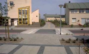
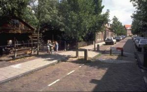
Driveway Links
A driveway link is a partial street closure, where the street character is
significantly changed so it appears roadway is narrowed and defined with textured
or colored paving. A ribbon curb or landscaping may be used to delineate roadway
edges. "Reclaimed" roadway area is converted to pedestrian facilities
and landscaping.
This is a very effective method of changing the initial impression of the
street. If done right, drivers will not be able to see through. It appears
as a road closure, yet allows through traffic.
The driveway link can provide access to small groups of homes and is especially
applicable to planned residential developments. The "go slow" feel
of the driveway link is enhanced by design standards that eliminate vertical
curb and gutter and use a relatively narrow driveway cross-section. A ribbon
curb may be used to protect roadway edges.
- Traffic diversion.
Traffic diversion is one of the most widely applied traffic-calming concepts.
It includes all devices that cause motor vehicles to slow and change direction
to travel around a physical barrier. Physical barriers used to divert traffic
in this fashion can range from traffic circles to trees planted in the middle
of the road. The discussion that follows provides information on: traffic
diverters, traffic circles, chicanes, and "tortuous" street alignments
as traffic-calming devices.
Traffic Diverters
Traffic diverters are physical barriers installed at intersections that
restrict motor vehicle movements into be a private drive. Typically, the selected
directions. The diverters may be designed to prevent right- or left-hand turns,
to block straight-ahead travel and force turns to the right or left, or create
a "T" intersection. In all cases, paths, cut-throughs, or other
provisions should be made to allow bicyclists and pedestrians access across
the closure.
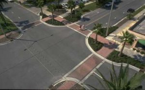
The splitter islands should be raised and landscaped to
prevent left-turning vehicles from taking a short cut to avoid
driving around the outside of the island.
Traffic diverters can take many forms. Here are two examples:
(1) Diagonal road closure/ diversion. Straight-through traffic
movements are prohibited. Motorists are diverted in one direction only.
Advantages:
- Through-traffic is eliminated.
- Area for landscaping is provided.
- Conflicts are reduced.
- Pedestrian safety is increased.
- Can include a bicycle pathway connection.
Disadvantages:
- Will inconvenience residents in gaining access to their properties.
- May inhibit access by emergency vehicles unless street names are
changed.
- Will move through traffic to other streets if not back to the arterial.
Example of an integrated traffic-calming plan.
Example:
Eugene, Oregon has used diagonal diverters with positive community response.
Eugene installs the diverters on a temporary basis to get neighborhood feedback
before making a permanent installation. Two types of diagonal diverters
are used &ndash some are landscaped, while others are just guardrails. Both types
have openings for bicycles. These have been supported by nearby residents.
Seattle installed truncated diagonal diverters, which allow right-turn movements
around one end of the diverter. The Engineering Department found that these
diverters were disruptive to neighborhood traffic and has focused instead
on installation of traffic circles to control neighborhood traffic problems.
Problems experienced with diverters included: (1) travel time and distance
increased for all users; (2) local residents were diverted to other streets;
(3) visitors and delivery services were often confused and delayed; and
(4) emergency vehicle response times were potentially increased.
(2) Turning-movement diverters. This type of diverter is designed to
prevent cutthrough traffic at the intersection of a neighborhood street with
a major street or collector. It prevents straight-through movements and allows
right turns only into and out of the neighborhood.
Advantages:
- Effective at discouraging cut-through traffic.
- Relatively low cost.
- Creates sense of neighborhood entry and identity.
Disadvantages:
- Limits resident access. Should be installed as part of overall neighborhood
circulation improvements to ensure reasonable convenience for residents.
- Motorists may try to override the diverter to make prohibited turns
unless vertical curbs, barriers, landscaping, or other means are used
to discourage such actions.
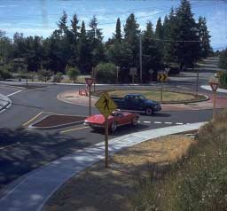
Traffic Circles
Small traffic circles (center island approximately 4 meters in diameter) can
be used as traffic-calming devices at intersections, reducing vehicle speeds.
A roundabout is a channelized intersection at which all traffic moves counterclockwise
around a central traffic island. These islands may be painted or domed, mountable
elements may be curbed, and may include landscaping or other improvements.
Advantages:
- Crashes reduced by 50 to 90 percent when compared to two-way and four-way
stop signs and other traffic signs by reducing the number of conflict
points at intersections.
- Effective in reducing motor vehicle speeds. Success, however, depends
on the central island being sufficiently visible and the approach lanes
engineered to deflect vehicles, preventing overrun of the island. Overrunnable
roundabouts on straight roads are less likely to produce the desired speed
reduction.
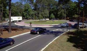
Traffic circles can be designed to accommodate large vehicles and emergency
access without undue restrictions.
Roundabout Accident Study
In 1989, a survey of crashes at mini-roundabouts examined years of crash data
for 447 sites in England, Wales, and Scotland. Key survey findings were:
- Mini-roundabouts were most commonly used on streets with speed limits
of 30 mph or less.
- Mini-roundabouts were found to have a far lower overall accident rate
than that of signalized intersections with equivalent speed limits.
- Looking only at crashes involving bicycles, the study showed that four-arm
mini-roundabouts have about the same involvement rate (accidents per million
vehicles of that type entering theintersection) as do conventional, four-legged,
signalized intersections.
Where possible, cyclists should be provided with cycle slips which enable
them to bypass speed humps.
Comparative Accident Rates:
Signalized intersections:
2.65 accidents/intersection/year
34 accidents per 100 million vehicles
20% resulted in serious or fatal injury
Roundabouts:
0.83 accidents/intersection/year
20 accidents per 100 million vehicles
19% resulted in serious or fatal injury
Both types of intersections compared have 30-mph speed limits and are four-legged
intersections.
Splitter islands are the islands placed within a leg of the roundabout, separating
entering and exiting traffic and designed to deflect entering traffic. They
are designed to prevent hazardous, wrong-way turning movements
These islands are important design elements and should be provided as a matter
of routine, wherever feasible. Without splitter islands, left-turning motorists
have a tendency to shortcut the turn to avoid driving around the outside of
the central island. The islands should, preferably, be raised and landscaped.
If this is not possible, painted island markings should be provided.
Design Considerations:
- Roundabouts should preferably have sufficiently raised and highly visible
centers to ensure that motorists use them, rather than overrunning.
- Clear signing is essential.
- Complementary speed reduction measures such as road humps on the approach
to roundabouts can improve safety.
- The design of roundabouts must ensure that bicyclists are not squeezed
by other vehicles negotiating the feature. Yet, where possible, adequate
deflection must be incorporated on each approach to enforce appropriate
entry speeds for motor vehicles.
Example: Seattle Neighborhood Traffic Control Program
The Seattle Engineering Department (SED) has experimented since the 1960's
with a variety of neighborhood traffic control devices. The major emphasis
of the SED Neighborhood Traffic Control Program is installing traffic circles
(roundabouts) at residential street intersections. City staff report that
about 30 circles are built each year. A total of approximately 400 circles
have been installed to date. Each circle costs about $5,000 to $6,000.
In Seattle, a traffic circle is an island built in the middle of a residential
street intersection. Each circle is custom-fitted to the intersection's geometry;
every circle is designed to allow a single-unit truck to maneuver around the
circle without running over it. A 2-foot concrete apron is built around the
outside edge of the circle to accommodate larger trucks. Large trucks, when
maneuvering around the circle, may run over the apron. The interior section
of the circle is usually landscaped.
SED coordinates the design and construction of each circle with the Seattle
Fire Department and school bus companies. Traffic circles are installed at
the request of citizens and community groups. Because there are more requests
than funding to build them, SED has created a system for evaluating and ranking
the requests. Before a request can be evaluated, a petition requesting a circle
must be signed by 60 percent of the residents within a one-block radius of
the proposed location. Then, the intersection's collision history, traffic
volume, and speeds are studied.
Chicanes
Chicanes are barriers placed in the street that require drivers to slow down
and drive around them. The barriers may take the form of landscaping, street
furniture, parking bays, curb extensions, or other devices. The Seattle Engineering
Department has experimented with chicanes for neighborhood traffic control.
It has found chicanes to be an effective means of reducing speed and traffic
volumes at specific locations under certain circumstances. A demonstration
project at two sets of chicanes showed:
- Reduction of traffic volumes on the demonstration streets.
- Little increase in traffic on adjacent residential streets.
- Reduced motor speeds and collisions.
- Strong support for permanent installation of chicanes by residents
(68 percent).
Design Considerations:
- Consideration should be given to safe bicycle travel. Bicycle bypasses
and signs to indicate directional priority are suggested.
- A reduction in sight lines should not be used in isolation to reduce
speeds, as alone, this could be potentially dangerous. A reduction in sight
lines may be appropriate to avoid excessive land taking or as a reinforcing
measure only where other physical features are employed that reduce speed.
- Chicanes offer a good opportunity to make environmental improvements
through planting. However, preference should be given to lowlying or slow-growing
shrubs to minimize maintenance and ensure good visibility.
- Measures should be employed to ensure that chicanes are clearly visible
at night.
- Where full closure or speed humps are not feasible, chicanes may be used
to reduce traffic speeds. Many different layouts are possible, including
staggered parking (on alternating sides of the road).
Tortuous Roads
Roads can be designed to meander or jog sharply, slowing traffic and limiting
views to discourage speeding. This technique can incorporate use of culde- sacs
and courtyards.
These pavement markings at a median refuge not only delineate the crossing
for motorists, but also cue pedestrians about the location of
the roadway edge.
Design Considerations:
Tortuous roads are generally planned as part of the design stage of a new road
layout, rather than being superimposed on an existing layout. The siting of
buildings is used to create a meandering road.
- Designers should be aware of the need for accessibility to residential
properties, both in terms of servicing and the needs of the individual.
Tortuous roads will prove to be unpopular if they severely restrict accessibility.
- Where traffic is deliberately diverted onto a tortuous route – to avert
town center congestion, for example – consideration should be given to maintaining
as direct a route as possible for bicyclists.
- Tortuous roads (a.k.a. serpentines) are under study, but have not yet
been approved for use in Portland. If approved, they would be limited for
use on two-lane or fewer residential streets.
- Road design is limited by AASHTO standards for transition taper lengths.
- This traffic-calming device may require significant parking removal and
should be used where parking removal is not an issue.
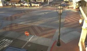
Pavement treatments can be applied to the entire traffic-calmed area or
limited to specific street uses. The texture or color should be
a noticeable contrast to the approaching roadways if speeds are
to be reduced.
- Surface texture and visual devices.
This category of traffic-calming devices includes signing, pavement marking,
colored and textured pavement treatments, and rumble strips. These devices
provide visual and audible cues about the traffic-calmed area. Colors and
textures that contrast with those prevailing along the roadway alert motorists
to the need for alertness, much as conspicuous materials increase bicyclist
and pedestrian visibility. Signs and pavement markings also provide information
about applicable regulations, warnings, and directions.
Signing and Pavement Markings
Installation of directional, warning, and informational signs and pavement
markings should conform to MUTCD guidelines, as applicable. Traffic-calming
devices may be new to many people in the United States and the signs and markings
will help minimize confusion and traffic conflicts.
Design Considerations:
- A part of the sign/pavement marking approach to mitigating traffic
in residential areas includes painting of stripes/lines on the roadway
and other patterns that are designed to have a psychological impact on
drivers. Although such patterns are basically intended to slow vehicles
rather than reduce traffic, they should make passage over residential
streets less desirable than if the roadway were untreated, in effect,
encouraging the use of alternative routes.
- Many of the patterns tried have had only marginal success. In a few
cases, the average speed increased slightly. A pattern that is successful
is that of painting transverse bands. Painted lines are applied to the
road at decreasing intervals approaching an intersection or "slow-down"
point. They are intended to give the impression of increasing speed and
motorists react by slowing down.
Pavement Texturing and Coloring
The use of paving materials such as brick, cobbles, concrete pavers, or other
materials that create variation in color and texture reinforces the identity
of the area as a traffic-restricted zone.
Model of a "woonerf"
Design Considerations:
- The choice of materials should ensure that they do not pose a danger
or deterrent to bicyclists. Cobbles present special difficulties, particularly
for vehicles with narrow wheels and without the benefit of suspension.
Such treatment is particularly discouraging for bicyclists on steep slopes,
making it harder to maintain momentum when riding uphill. Thus, as a general
rule, cobbles should not be employed. Similarly, pavers with chamfered
edges impair a bicyclist's stability and should be avoided.
- The color and texture of the street surface are important aspects of
the attractiveness of many residential streets. The variation from asphalt
or concrete paving associated by most people with "automobile territory"
signals to the motorist that he or she has crossed into a different, residential
zone where pedestrians and bicyclists can be expected to have greater
priority.
Putting the Design Techniques to Work: Selected Examples of Traffic
Calming
Most traffic-calmed streets utilize a combination of the devices just discussed.
The following are some examples: the woonerf, entry treatments, shared streets,
and other techniques (bicycle boulevards, modified street design, modified intersection
design, channelization changes, traffic calming on a major road, slow streets,
transit streets, and pedestrian zones).
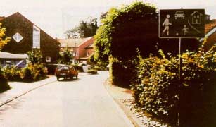
The distinction between sidewalks and roadway is blurred in woonerfs.
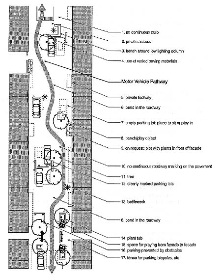
- The woonerf.
A woonerf (or "living yard") combines many of the trafficcalming
devices just discussed to create a street where pedestrians have priority
and the line between "motor vehicle space" and "pedestrian
(or living) space" is deliberately blurred (see the model of a woonerf).
The street is designed so motorists are forced to slow down and exercise caution.
Drivers, the Dutch say, do not obey speed limit signs, but they do respect
the design of the street.
The woonerf (plural – woonerven) is a concept that emerged in the 1970's as
increased emphasis was given by planners to residential neighborhoods. People
recognized that many residential streets were unsafe and unattractive and
that the streets, which took up a considerable amount of land area, were used
for nothing but motor vehicle access and parking. Most of the time, the streets
were empty, creating a "no-man's land" separating the homes from
one another.
The Dutch, in particular, experimented extensively with street design concepts
in which there was no segregation between motorized and non-motorized traffic
and in which pedestrians had priority.
A law passed in 1976 provided 14 strict "design rules" for woonerfs
and resulted in construction of 2,700 such features in the following seven
years.
The woonerven were closely evaluated, with the/ following findings:
- Injury accidents were reduced by 50 percent.
- Vehicle speeds were reduced to an average of 8 to 15 mph (13 to 25
km/h).
- Nationally, 70 percent of the Dutch population thought woonerven to
be attractive or highly attractive.
- Non-motorized users assessed woonerven more positively than motorized
users.
- Feedback from residents living on woonerfs was very positive. They
appreciated the low traffic volumes and absence of cut-through traffic,
but considered the larger play areas and other improvements to the street
environment to be even more important benefits.
Woonerf Design Principles:
Following evaluation of the woonerven, the Dutch law was amended (July
1988) to allow greater design flexibility, replacing the design rules with
six basic principles.
(1) The main function of the woonerf shall be for residential purposes. Thus,
roads within the "erf" area may only be geared to traffic terminating
or originating from it. The intensity of traffic should not conflict with
the character of the woonerf in practical terms: conditions should be optimal
for walking, playing, shopping, etc. Motorists are guests. Within woonerven,
traffic flows below 100 vehicles per hour should be maintained.
(2) To slow traffic, the nature and condition of the roads and road segment
must stress the need to drive slowly. Particular speed-reduction features
are no longer mandated, so planners can utilize the most effective and appropriate
facilities.
(3) The entrances and exits of woonerven shall be recognizable as such from
their construction. They may be located at an intersection with a major road
(preferable) or at least 20 meters (60 feet) from such an intersection.
(4) The impression shall not be created that the road is divided into a roadway
and sidewalk. Therefore, there shall be no continuous height differences in
the cross-section of a road within a woonerf. Provided this condition is met,
a facility for pedestrians may be realized. Thus, space can be designated
for pedestrians and a measure of protection offered, for example, by use of
bollards or trees.
(5) The area of the road surface intended for parking one or more vehicles
shall be marked at least at the corners. The marking and the letter "P"
shall be clearly distinguishable from the rest of the road surface. In shopping
street "erfs" (winkelerven), special loading spaces can be provided,
as can short-term parking with time limits.
(6) Informational signs may be placed under the international "erf"
traffic sign to denote which type of "erf" is present.
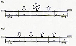
The conversion of a 58-foot roadway. Elimination of one travel lane
in each direction creates space for bicyclists.
- Entry treatment across intersections.
Traffic-calming devices can be combined to provide an entry or "gateway"
into a neighborhood or other district, reducing speed though both physical
and psychological means. Surface alterations at intersections with local streets
can include textured paving; pavement inserts; or concrete, brick, or stone
materials. At the entry, the surface treatment can be raised as high as the
level of the adjoining curb. Visual and tactile cues let people know that
they are entering an area where motor vehicles are restricted.
Eugene, Oregon installs curb extensions at entrances to neighborhood areas,
usually where a residential street intersects an arterial. The curb extension
is placed to prevent motor vehicle traffic from cutting through the neighborhood.
The curb extension is signed as a neighborhood entrance or exit. Most of the
street remains two-way, but one end becomes a one-way street. Compliance by
motor vehicles is mostly good. Bikes are allowed to travel both ways at all
curb extensions.
- Bicycle boulevards.
The City of Palo Alto, California has moved beyond spot traffic-calming treatments
and has created bicycle boulevards – streets on which bicycles have priority.
The purpose of a bicycle boulevard is to provide:
- Throughway where bicycle movements have precedence over automobiles.
- Direct route that reduces travel time for bicyclists.
- Safe travel route that reduces conflicts between bicyclists and motor
vehicles.
- Facility that promotes and facilitates the use of bicycles as an alternative
transportation mode for all purposes of travel.
The Palo Alto bicycle boulevard is a 2-mile stretch of Bryant Street – a residential
street that runs parallel to a busy collector arterial. It was created in
1982 when barriers were fitted to restrict or prohibit through motor vehicle
traffic, but to allow through bicycle traffic. In addition, a number of stop
signs along the boulevard were removed. An evaluation after 6 months showed
a reduction in the amount of motor vehicle traffic, a nearly twofold increase
in bicycle traffic, and a slight reduction in bicycle traffic on nearby streets.
The City also found that anticipated problems failed to materialize and concluded
that a predominately stop-free bikeway – on less traveled residential streets
– can be an attractive and effective route for bicyclists. The bicycle boulevard
bike traffic increased to amounts similar to those found on other established
bike routes.
The bicycle boulevard continues to function as a normal local city street,
providing access to residences, on-street parking, and unrestricted local
travel. The City received complaints about the visual appearance of the initial
street closure barriers (since upgraded with landscaping), but is unaware
of any other serious concerns of nearby residents.
Plans for the extension of the bicycle boulevard through downtown Palo Alto
were approved by the City Council in the summer of 1992. Included in this
extension was the installation of a traffic signal to help bicyclists cross
a busy arterial.
- Channelization changes.
The Seattle Engineering Department is changing some of its streets from four
lanes to two lanes. with a center left-turn lane. These channelization changes
can provide extra room for bicycle lanes or a wide lane for cars and bikes
to share.
Numerous comments from users of some of those streets say motor vehicle speeds
seem to have decreased. One street in particular, Dexter Avenue North, is
a popular commuting route to downtown Seattle for bicyclists.
Traffic counts on the street show bicyclists make up about 10 to 15 percent
of the traffic at certain times during the day. The rechannelization had little
or no effect on capacity, reduced overtaking accidents, and made it easier
for pedestrians to cross the street (by providing a refuge in the center of
the road).
11.5 Exercise
Do one of the following exercises:
- Choose a site-specific location (such as two to three blocks of a local
street) where fast traffic or short cuts are a problem. Conduct a site analysis
to determine problems. Prepare a detailed site solution that incorporates
several traffic-calming devices. Illustrate with drawings and describe the
anticipated changes in traffic speed.
- Prepare a traffic-calming solution for an entire neighborhood or downtown
area that illustrates an area-wide approach to slowing traffic. Conduct a
site analysis to determine problem areas. Illustrate your solutions and describe
the anticipated changes in traffic speed and flow.
11.6 References
Text and graphics for this lesson were derived from the following sources:
Federal Highway Administration, National Bicycling and Walking Study-Case
Study No. 19: Traffic- Calming, Auto-Restricted Zones, and Other Traffic Management Techniques-Their Effects on Bicycling and Pedestrians, 1994.
Federal Highway Administration, Pedestrian & Bicyclist Safety
and Accommodation-Participation Handbook, NHI Course #38061, 1996.
Hass Klau, Illustrated Guide to Traffic Calming, Institute of Transportation
Engineers, 1990.
For more information on this topic, refer to:
J. Cleary, Cyclists and Traffic Calming, Cyclists Touring Club, Godalming,
U.K., 1991.
R. Ewing and Kooshian, "U.S. Experience With Traffic Calming," ITE
Journal, August 1997, pp. 28- 33.
Cynthia Hoyle, Traffic Calming, Planning Advisory Service Report No.
456, American Planning Association, 1995.
Institute of Transportation Engineers, Recommended Guidelines for
the Design and Application of Speed Humps, 1993.
National Cooperative Highway Research Program (NCHRP), Research Synthesis
on Roundabouts, NCHRP Synthesis 264.
Traffic Calming in Practice – An Authoritative Sourcebook With 85
Illustrative Case Studies (available through ITE), Landor Publishing, London,
1994.

