U.S. Department of Transportation
Federal Highway Administration
1200 New Jersey Avenue, SE
Washington, DC 20590
202-366-4000
The focus of this chapter is on safety improvements to the most permanent infrastructure features. Although traffic safety analysts and highway designers generally think in terms of the roadway (travel lanes) separately from the roadside (shoulders and beyond), this chapter considers the roadway in a more generic sense. The roadway in this context is the land and improved surface over which vehicles travel, including the paved surface—lanes and shoulders—and extending to the drainage structures and safety hardware. This definition also includes all the materials and structures that support the paved surface and prolong its operating life.
This chapter includes safety improvements specific to this broad definition of the roadway, focusing on the surfaces and hardware that may contribute to a crash or reduce its severity, rather than traffic control devices that communicate visual information to the driver, which are covered in the next chapter. This chapter also includes treatments that provide additional roadway capacity or operational safety benefits.
Highway professionals apply guidelines and engineering judgment to design roadways that maximize the effectiveness and safety of the interactions between vehicles and the roadway and between drivers and the roadway. This complicated balance considers the roadway's function (traffic volume, vehicle mix, and design speed) and geometrics (curvature, grades, lane, and shoulder width). Design elements are added to mitigate safety risks due to roadway design constraints (geography, right of way availability, construction, and operating costs). In some cases, crashes may occur or persist at certain roadway locations due to the geometrics of the road and the actual vehicle volumes and traffic mix. The following safety practices mitigate safety risks for all vehicles, including CMVs.
Horizontal curves and roadway sections involving speed transitions can present challenges for drivers to negotiate, and repeated traffic can reduce the friction of the pavement precisely at the locations where it is most needed for vehicle control and braking.(12,13) Wet driving conditions can increase the risks of crashes with reduced-friction pavements. These challenges are compounded for CMVs, which are heavier and have higher centers of gravity. While traditional friction surface layers can address this issue for long segments of roadways, HFSTs are appropriate for critical locations with parameters known for these types of crashes, such as intersections, curves, and ramps, as shown in figure 3. The HFSTs can be a cost-effective alternative to changing the curvature or correcting superelevation of the roadway and do not induce increased speeds as these more traditional countermeasures do. The HFSTs have a proven life-cycle cost benefit.(13,14)
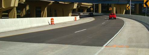
Source:
The Transtec Group. Pavement Treatment Reduces Crashes.(15)
Figure 3
Photo. High-friction surface treatment on a ramp in Wisconsin.
The HFSTs involve the application of a thin layer of durable, very high-friction aggregate onto a bed of specially engineered resin or polymer binder. The binder locks the aggregates firmly in place, creating a durable surface that greatly increases friction in locations where the demand is high such as horizontal curves, intersections, ramps, steep grades, or combinations of these. The treatment is typically applied in short lengths and can be installed by machine or by hand with short cure times and minimal effects on traffic. The HFST applications have been tested to provide improved friction over a 10-year period, so the relatively higher cost of HFSTs (compared to other friction surface treatments) is offset by the small amount of material needed for the focused application and its demonstrated effects on crash reduction. The HFST technical assistance to States is available through the FHWA Every Day Counts initiative.(14) The FHWA is working with State organizations and industry through the American Traffic Safety Services Association High Friction Surfacing Council to revise the American Association of State Highway and Transportation Officials (AASHTO) provisional specification and encourage use of HFST. Application of this countermeasure at interchange ramps has demonstrated excellent reduction in large truck crashes in Illinois and California.
Cost-Effectiveness Assessment: HFSTs are assessed as proven and low to moderate cost.
Another issue with curves is the design of the slopes to help drivers comfortably and safely negotiate the curve. Design guidelines provide standards to transition from the normal pavement crown to a superelevated section near the beginning of a curve and back to the normal crown near the end. The shoulder cross-slope may not follow the superelevation, depending on drainage and other design considerations. This break in the cross-slope can be an issue for vehicle stability, particularly for vehicles with a high center of gravity such as CMVs. The difference between the cross-slope of the shoulder and the cross-slope of the adjacent travel lane is called the roll-over, shown in figure 4.(16) American Association of State Highway and Transportation Officials (AASHTO) design guidelines call for a maximum roll-over of no greater than 8 percent.(17,18) Use of a rounded shoulder may alleviate some of the concern associated with large cross-slope breaks.
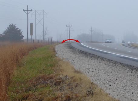
Source:
Stein, W., and Neuman, T. Mitigation Strategies for Design Exceptions.(17)
Figure 4
Photo with illustration. Cross-slope break on a superelevated curve.
In response to recommendations from a National Transportation Safety Board (NTSB) report regarding a cargo tank rollover crash in 2009, FHWA issued a memorandum reminding agencies of these design considerations and encouraged geometric improvements at identified or probable problem locations rather than system-wide as these crashes are relatively rare.(19,20,21) Education on this topic may be helpful for construction and maintenance personnel who need to be aware why this detail is important to construct correctly and maintain during pavement overlays.
Cost-Effectiveness Assessment: Cross-slope breaks are assessed as tried and moderate cost.
Roadways are engineered to allow precipitation to drain away from the pavement surface, with standards and guidelines for the pavement cross slopes. Drainage is necessary not only to remove water from the surface and reduce its effects on safe vehicle handling (hydroplaning and loss of friction), but to drain away water from the roadway structure to reduce the degradation of the pavement subsurface and grading, which can lead to pavement failures. Wet roadway surfaces pose problems for heavier CMVs that are more difficult to maneuver in adverse weather (which can result in overcorrections and pose risks to other vehicles on the roadway).
In urban sections, water often drains into storm sewers and off bridge structures; in rural roadways with more right of way, water drains off shoulders and away from roadways into ditches designed to move the water. In order to maintain proper drainage and prevent water pooling, drainage structures need to be calibrated to local weather conditions (frequency and intensity of rain events and consideration of melting snow), and shoulders and drainage ditches and culverts require maintenance to properly channel water away from the roadway.(22,23)
Areas most prone to water pooling are the inside of curves and tunnel entrances and other restricted areas. In these locations, road owners use slot drains to capture the water and prevent continual freeze-thaw cycles that can damage the pavement and result in icy driving conditions. These enhanced drainage treatments involve higher costs due to the infrastructure intervention involved but can be beneficial in certain locations with observed drainage issues and crash frequencies.
Cost-Effectiveness Assessment: Enhanced drainage is assessed as tried and moderate cost.
Longitudinal barriers along the roadside or median are designed to contain and redirect vehicles in a controlled manner. These barriers are used where leaving the roadway will likely result in a more severe crash. They keep vehicles from crossing into oncoming traffic, prevent vehicles from rolling over on steep slopes, keep vehicles on bridges and ramps and protect traffic under those structures, and prevent vehicles from hitting roadside objects. Since 1993, these barriers and all other roadside hardware have been tested for effectiveness under NCHRP Report 350: Recommended Procedures for the Safety Performance Evaluation of Highway Features, which specifies a range of test levels for roadside hardware for certain vehicles at certain speeds.(24) AASHTO's new Manual for Assessing Safety Hardware updates these tests to accommodate changes in the vehicle fleet.(25)
The first three test levels, TL-1, TL-2, and TL-3, require successful tests of a small car and a pickup truck at speeds of 31 mph, 43 mph, and 62 mph, respectively. Where a greater percentage of large vehicles are present or the risk of penetration through the barrier has higher consequences, agencies may choose to use barriers that have been crash-tested with larger vehicles. The TL-4 adds a single-unit truck at 56 mph to the TL-3 requirements; TL-5 substitutes a tractor/van trailer for the single-unit truck; TL-6 substitutes a tractor-tank trailer. TL-3 has typically been used for roadways posted above 45 mph for many years, although not all older systems have yet been replaced.
Higher-performance barriers (those at TL-4 or higher) are more likely to contain a large vehicle effectively. Each successive test level requires more substantial and typically taller structures. Highway and bridge designers should consider overall CMV volumes, vehicle mix, and the nature of the risk associated with different roadway corridors and bridges to determine where the additional cost is justified. Barriers that can contain CMVs under the test criteria may also be so rigid as to pose increased crash severity risk for the larger number of passenger vehicles compared to more flexible systems typically associated with the lower crash-testing levels, so this balance must be kept in mind. The costs of higher-performance barriers can vary based on a number of factors. For example, modifying existing barriers is typically not cost-effective and may actually cost more than installing new barrier because the existing barrier often needs to be removed or modified to add strength with reinforcing steel between the existing and new concrete. Another example is where concrete barrier is needed in a median to limit deflection into an opposing travel lane; this is significantly more expensive than a flexible or semi-rigid barrier. However, if new concrete barriers are to be installed, which is common on urban freeways, much of the cost for the new barrier is in the mobilization of equipment, drainage and storm water management, and building the foundation. In these cases strong consideration should be given toTL-5 barriers, since the additional cost is incremental and occupant risk is virtually unchanged while the barrier serves a greater percentage of the CMV fleet (Figure 5). The TL-6 structures are significantly more expensive and will likely be limited to certain high-risk locations.
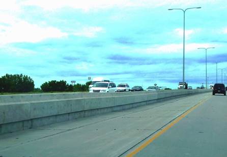
Source:
FHWA.
Figure 5
Photo. TL-5 concrete median barrier.
Cost-Effectiveness Assessment: Higher-performance barriers are assessed as proven and moderate to high cost.
Rumble Strips and Lane Departure Warning Systems
Rumble strips are a series of milled or raised elements applied at center lines, edge lines, or shoulders (Figure 6) to alert drivers who are leaving their travel lane. They are primarily intended to address crashes caused by driver inattention and fatigue. The CMV drivers are susceptible to fatigue-related safety risks, given the longer hours of operation or longer distances of travel and the financial pressures to maximize driving time allowed by hours of service regulations. Rumble strips are proven to significantly reduce fatal and injury head-on collisions and single-vehicle run-off-the-road crashes.(26,27,28) Analysis results indicate approximately 40 percent reduction in single-vehicle run-off-the-road crashes involving heavy vehicles (i.e., trucks) on rural freeways.(26) Since drowsy and distracted drivers can drift from their lane at any location, this crash countermeasure is applied systemically rather than at specific locations.
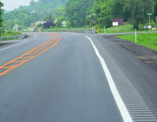
Source: Hughes, W.,
Jagannathan, R. and Gross, F., 2008. Two Low-Cost Safety
Concepts for
Two-Way STOP-Controlled, Rural Intersections on High-Speed
Two-Lane, Two-Way
Roadways. (29)
Figure 6
Photo. Milled shoulder rumble strip.
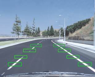
Recent research has demonstrated the benefits of onboard lane departure systems (Figure 7), or virtual rumble strips. These systems can detect lane departures and offer driver feedback through steering wheel vibration, lights or audio warnings, and even steering correction. Driver simulation studies indicate that virtual rumble strips may be more effective than physical pavement rumble strips for providing safety feedback to sleepy CMV drivers.(30) Lane departure systems are being implemented in more new vehicles as a safety option and are a necessary precursor to more advanced driver-assisted and automated vehicle operations. Truck manufacturers are offering more lane departure systems to motor carriers and are developing the systems as part of a suite of services to offer broader driver assistance as a pathway to more autonomous CMV operations. Continued use of physical rumble strips will be necessary until most of the vehicle fleet has lane departure warning systems.
Source: Halvorson,
B. IIHS: Avoidance Systems Could Cut Fatal Crashes by One-Third. The Car
Connection. Photo ©2016 Nissan.(31)
Figure 7
Photo with illustration. Lane departure warning system (virtual rumble strip).
Cost-Effectiveness Assessment: Rumble strips and lane departure warning systems are assessed as proven and low cost.
Given their size and weight, CMVs present different operational characteristics over the road than passenger vehicles and light-duty trucks: they require longer distances to brake, accelerate more slowly, and negotiate steeper grades more slowly. These differences can lead to operational conflicts between passenger vehicles and CMVs and can cause automobile drivers to perform risky maneuvers to avoid slower CMVs. In some cases, geography and topography result in roadway segments with long, steep grades, which cause CMVs to slow significantly on uphill sections and can lead to unsafe acceleration and braking on downhill sections. The following safety improvements are related to expanding the roadway infrastructure to mitigate the risks of CMV interactions with other vehicles in such circumstances.
Downhill grades, even designed according to AASHTO guidelines, can pose operational risks for CMV drivers. Downhill operations require drivers to observe proper braking procedures (to avoid degrading braking system performance) and proper brake maintenance more than in ascents If extended downhill grades are accompanied by sharp curves and switchbacks, more frequent braking may accelerate braking system failures. The CMVs with failed or degraded braking systems can pose serious crash risks to CMV drivers and to other traffic.
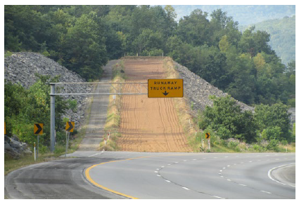
Since the 1950s, States have built escape ramps—exclusive facilities to control runaway vehicles by diverting them from the main traffic lanes and dissipating their energy through gravitational deceleration, rolling resistance (gravel beds), or both.(32) The escape ramps (Figure 8) require extra right of way and must be constructed to fit within the downhill slopes of the roadway.(33,34)
Source:
FHWA. Designing for Transportation Management and Operations: A Primer.(35)
Figure 8
Photo. Truck escape ramp.
The CMV safety professionals are also mitigating these downhill risks by changing commercial driver's license training curricula to instruct drivers on braking procedures that control vehicle speeds while allowing braking system components to dissipate energy and maintain functionality. The CMV safety enforcement agencies also pay attention to braking system components in roadside safety inspections to encourage motor carriers and drivers to pay attention to signs of braking system problems.
Cost-Effectiveness Assessment: Escape ramps are assessed as proven and high cost.
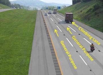
Large vehicles can present problems for other traffic on hilly terrain and may lead to risky passing behavior with limited sight distances. Climbing lanes provide additional capacity on uphill grades to allow faster traffic to pass slower traffic without the increased risk of making the passing maneuver in the opposing traffic lane. Highway professionals use climbing lanes (Figure 9) of varying lengths and spacing, depending on the truck volumes, overall traffic levels, shoulder widths, and right of way availability.(27,36)
Source:
New York State Thruway Authority and Canal Corporation. Highway
Improvements Report: Tappan Zee Bridge/I-287 Corridor Project.(37)
Figure 9. Photo with illustration. Climbing lane on I-81 in Virginia.
Alternate passing lanes have three lanes of traffic (two directions of travel), shown in figure 10. The center lane alternates as a passing lane in one travel direction. The center and right lanes merge back into one lane, and then the center lane serves as a passing lane for traffic in the opposite direction. The alternate passing lanes in Missouri, sometimes called a shared four-lane road, feature wider than normal center striping with two sets of rumble stripes within 4-foot medians and a series of signs accompanying the beginning and ending of the lanes. This design provides increased capacity and improved safety at significantly less cost than providing four lanes in each direction.
Source: Missouri
Department of Transportation. Shared Four Lane Brochure.(38)
Figure 10. Illustration. Alternate Passing Lane.
Newer CMVs are being manufactured with engines with better weight-to-horsepower ratios, allowing CMVs more power to negotiate moderate changes in highway grades. Since climbing and alternate passing lanes involve more paved roadway surface, their cost can limit their cost-effectiveness to being applied in limited, targeted instances.
Cost-Effectiveness Assessment: Climbing lanes and alternate passing lanes are assessed as proven and high cost.
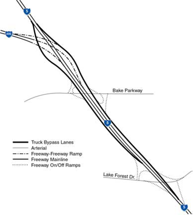
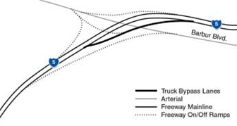
Some freeway interchanges (freeway to freeway [Figure 11] and freeway to arterial [Figure 12]) are situated in regions with steep grades, affecting the ability of CMVs to travel fast enough through the interchange to merge with other high-speed traffic. Interchange bypasses are facilities that separate large vehicles around or through a major interchange area, allowing CMVs to negotiate grades and creating safer, easier merging lanes onto major roadways.(36)
Source: Douglas, J.G. Handbook
for Planning Truck Facilities on Urban Highways.(39)
Figure 11
Map. Interchange bypass at I-5/I-405 in Orange County, California.
Source:
Douglas, J.G. Handbook for Planning Truck Facilities on Urban Highways.(3936)
Figure 12
Map. Interchange bypass at Tigard interchange in Oregon.
These separate roadway facilities can offer operational benefits and avoid multivehicle collisions involving slower-moving CMVs. This high-cost countermeasure may have applicability for certain interchanges with high truck volumes and unique topography. The cost is dependent on many factors such as the number of additional lanes, complexity and length, right of way costs, and environmental clearances.
Cost-Effectiveness Assessment: Interchange bypasses are assessed as tried and high cost.
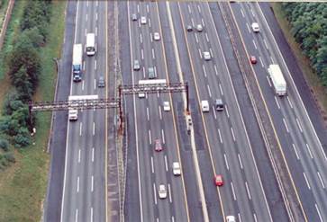
The New Jersey Turnpike implemented a dual-dual facility, with an inner and outer roadway in each direction. The inner roadway is reserved for passenger vehicles, while the outer roadway is open to all vehicle types. In this 35-mile segment, 23 miles has three lanes in each direction for both the interior and exterior roadways, while another 12 miles has two lanes on the exterior roadway and three lanes on the interior roadway. Each roadway has 12-foot lanes and shoulders, and the inner and outer roadways are barrier separated, as shown in figure 13.
Source: Collier, T., Goodin, G. Managed lanes: A
cross-cutting study.(40)
Figure 13
Photo. Dual-dual section of the New Jersey Turnpike.
States have been studying the application of exclusive truck roadways with various permutations: tolled truck-only lanes and truck-only lanes that allow longer combination vehicles or vehicles exceeding Federal weight limits. These facilities are expected to offer motor carriers operational benefits of increased productivity and greater travel time reliability, and to potentially offer safety benefits.(36,41,42) However, there are no domestic examples of exclusive truck-only freeways to test for safety benefits, which would likely differ from the New Jersey dual-dual section by assigning the inner roadway exclusively to trucks rather than passenger vehicles. Some studies have used micro-simulations of truck and truck-auto operations to estimate the safety effects of the absence of truck-auto interactions, while others have used statistical tools to estimate the safety benefits.
Motor carriers and truck drivers are less supportive of tolled truck-only facilities, and not all motor carriers are interested in truck-only lanes that allow longer or heavier vehicles because some carriers would have to purchase new equipment to take advantage of the productivity gains Increasing freight demand in the long term may create an environment in which highway professionals and motor carriers expand their interest in exclusive truck roadways to move more freight with less congestion. New research techniques are being investigated to estimate the safety benefits from these new facilities.
Cost-Effectiveness Assessment: Exclusive truck roadways are assessed as experimental/promising and high cost.
| << Previous | Table of Contents | Next >> |

