U.S. Department of Transportation
Federal Highway Administration
1200 New Jersey Avenue, SE
Washington, DC 20590
202-366-4000
| < Previous | Table of Content | Next > |
There are a variety of ways to accommodate bicycles on roadways. In many cases, a few simple construction projects can make a big difference, such a replacing unsafe drain grates, filling potholes, or maintaining roadway shoulders so that they are free of debris. The next few lessons explore design solutions for several types of on-road bicycle facilities, as well as other general improvements that can be made to make bicycling on roadways safer and easier.
Lessons 18 through 20 cover the following bicycle facility types:
The text and graphics for this lesson were derived from the Oregon Bicycle and Pedestrian Plan, a statewide planning policy and design manual published by the Oregon Department of Transportation in 1995. Oregon has been a leader among the States in bicycle facility development. More detailed information on facility design is provided in AASHTO's Guide for the Development of Bicycle Facilities (1999).
Since bicyclists are legally able to use all roadways, all roads are technically classified as "shared roadways" (with the exception of controlled-access freeways in some States). AASHTO defines a shared roadway as "a roadway which is not officially designated and marked as a bicycle route, but which is open to both bicycle and motor vehicle travel. This may be an existing roadway, street with wide curb lanes, or a road with paved shoulders." (AASHTO, 1998)
In the United States, most shared roadways have no provisions for bicycle travel and are, therefore, perceived as unsafe by many bicyclists. However, there are some design measures that can be taken to ensure that shared roadways accommodate bicyclists safely and efficiently. This lesson describes several design options for shared roadways, including wide curb lanes, shoulder bikeways, and bicycle boulevards. There is also a discussion of practices to be avoided, such as sidewalk bikeways.
Bike lanes are another design treatment preferred by many bicyclists - they are addressed separately in Lessons 19 and 20.
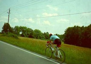
Shared roadway.
There are no specific bicycle standards for most shared roadways; they are simply the roads as constructed. Shared roadways function well on local streets and minor collectors, and on lowvolume rural roads and highways. Mile per mile, shared roadways are the most common place for people to ride.
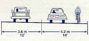
To be effective, a wide lane must be at least 14 ft wide, but less than
16 ft wide.
Shared roadways are suitable in urban areas on streets with low speeds – 40 km/h (25 mph) or less – or low traffic volumes (3,000 average daily traffic (ADT) or less, depending on speed and land use).
In rural areas, the suitability of a shared roadway decreases as traffic speeds and volumes increase, especially on roads with poor sight distances. Where bicycle use or demand is potentially high, roads should be widened to include shoulder bikeways if the travel speeds and volumes on the roadway are high.
Many urban local streets carry excessive traffic volumes at speeds higher than they were designed to carry. These can function as shared roadways if traffic speeds and volumes are reduced. There are many traffic-calming techniques that can make these streets more amenable to bicycling on the road.
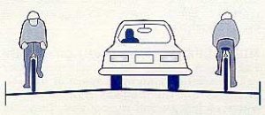
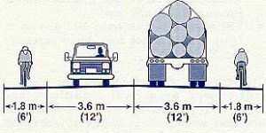
Wide curb lane.
A wide curb lane may be provided where there is inadequate width to provide bike lanes or shoulder bikeways. This may occur on retrofit projects where there are severe physical constraints and all other options have been pursued, such as removing parking or narrowing travel lanes. Wide curb lanes can often be installed by narrowing inner lanes on a multi-lane arterial, thereby re-allocating roadway space so that the outside (curb) lanes are wider (see Lesson 20 for roadway retrofit solutions). Wide curb lanes are not particularly attractive to most cyclists, they simply allow motor vehicles to pass cyclists within a travel lane.
To be effective, a wide lane must be at least 4.2 meters (14 feet) wide, but less than 4.8 meters (16 feet) wide. Usable width is normally measured from the curb face to the center of the lane stripe, but adjustments need to be made for drainage grates, parking, and the ridge between the pavement and gutter. Widths greater than 4.8 meters (16 feet) encourage the undesirable operation of two motor vehicles in one lane. In this situation, a bike lane or shoulder bikeway should be striped.
Paved shoulders are provided on rural highways for a variety of safety, operational, and maintenance reasons:
Shoulder Bikeway: Min 3.5 meters (5 feet) against curb, parking, or guardrail;
1.2 meters (4 feet) against the open shoulder.
In general, the shoulder widths recommended for rural highways in AASHTO's Policy on Geometric Design of Highways and Streets serve bicyclists well, since wider shoulders are required on heavily traveled and high-speed roads and those carrying large numbers of trucks.
When providing shoulders for bicycle use, a width of 1.8 meters (6 feet) is recommended, however even 0.6 meters (2 feet) of shoulder width will benefit more experienced riders. A 1.8-meter (6-foot) wide shoulder allows a cyclist to ride far enough from the edge of the pavement to avoid debris, yet far enough from passing vehicles to avoid conflict. If there are physical width limitations, a minimum width of 1.2 meters (4 feet) from the longitudinal joint between a monolithic curb and gutter and the edge of travel lane may be adequate.
On steep grades, it is desirable to maintain a 1.8 meter (6-foot) wide shoulder (minimum - 1.5-meters or 5 feet), as cyclists need more space for maneuvering.
Many existing gravel shoulders have sufficient width and base to support shoulder bikeways. Minor excavation and the addition of 75 to 100 millimeters (3 to 4 inches) of asphaltic concrete is often enough to provide shoulder bikeways. It is best to widen shoulders in conjunction with pavement overlays for several reasons:
When shoulders are provided as part of new road construction, the pavement structural design should be the same as that of the roadway.
On shoulder-widening projects, there may be some opportunities to reduce costs by building to a lesser thickness. A total of 50 to 100 millimeters (2 to 4 inches) of asphalt and 50 to 75 millimeters (2 to 3 inches) of aggregate over existing roadway shoulders may be adequate if the following conditions are met:
The Joint Between the Shoulders and the Existing Roadway The following techniques should be used to add paved shoulders to roadways where no overlay project is scheduled:

Saw-cut joint.
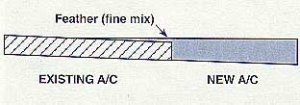
Asphalt feathering.
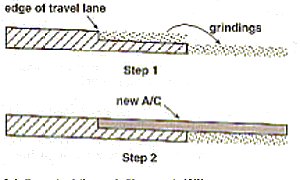
Grinding out existing asphaltic concrete (A/C).
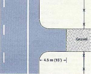
Paved driveway apron.
Wherever a highway is constructed, widened, or overlaid, all gravel driveways and approaches should be paved back 4.5 meters (15 feet) to prevent loose gravel from spilling onto the shoulders.
Bike routes are specially designated shared roadways that are preferred for bicycle travel for certain recreation or transportation purposes. AASHTO's Guide for the Development of Bicycle Facilities cites the following reasons for designating bike routes:
Bike route signs may also be used on streets with bike lanes, as well as on off-road trails. Regardless of the type of facility or roadway they are used on, it is recommended that bike route signs always include destination, direction, and distance information.
The signing of shared roadways indicates to bicyclists that there are particular advantages to using these routes compared to alternate routes. This means the responsible agencies have taken action to ensure that these routes are suitable as shared routes and will be maintained. Routes should be considered for signing only if some of the following criteria are met:
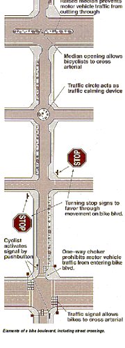 Elements of a bike boulevard, including street crossings. |
The bicycle boulevard is a refinement of the shared roadway concept-the operation of a local street is modified to function as a through-street exclusively for bicycles, while maintaining local access for automobiles. Traffic-calming devices reduce traffic speeds and through trips. Traffic controls limit conflicts between motorists and bicyclists, and give priority to through-bicycle movement.
Successful bicycle boulevard implementation requires careful planning with residents and businesses to avoid unacceptable impacts.
The Oregon Department of Transportation has more than 20 years of experience designing bikeways, and has also learned from local city and county experiences. Some practices have proven to be poor ones:
Some early bikeways used sidewalks for both pedestrians and bicyclists. While in rare instances this type of facility may be necessary, or desirable for use by small children, in most cases, it should be avoided. Sidewalks are not suited for bicycling for several reasons:
Bicyclists are safer when they are allowed to function as roadway vehicle operators, rather than as pedestrians.
Where constraints do not allow full-width walkways and bikeways, solutions should be sought to accommodate both modes (e.g., narrowing travel lanes or reducing on-street parking). In some urban situations, preference may be given to accommodating pedestrians. Sidewalks should not be signed for bicycle use – the choice should be left to the users.
Raised concrete curbs create an undesirable condition when used to separate the motor vehicle lane from a bike lane or paved shoulder: Either one may hit the curb and lose control, with the motor vehicle crossing onto the bikeway or the cyclist falling onto the roadway.
At night, the curbs cast shadows on the lane, reducing the bicyclist's visibility of the surface. Extruded curbs make bikeways difficult to maintain and tend to collect debris. They are often hit by motor vehicles, causing them to break up and scatter loose pieces onto the surface.
These can deflect a bicycle wheel, causing the cyclist to lose control. If pavement markers are needed for motorists, they should be installed on the motorist's side of the stripe, and they should have a beveled front edge.
Care must be taken to ensure that drainage grates are bicycle-safe. If not, a bicycle wheel may fall into a slot in the grate, causing the cyclist to fall. Replacing existing grates (See A and B in figure below [preferred methods]) or welding thin metal straps across the grate perpendicular to the direction of travel (C, alternate method) is required. These should be checked periodically to ensure that the straps remain in place.
Note: Grates with bars perpendicular to the roadway must not be placed at curb cuts, as wheelchairs could get caught in the slots.
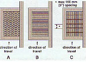
Bicycle-safe grates.
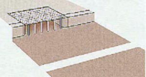
Inlet flush in the curb face.
The most effective way to avoid drainage grate problems is to eliminate them entirely with the use of inlets in the curb face (see figure above).
If a street-surface grate is required for drainage, care must be taken to ensure that the grate is flush with the road surface. Inlets should be raised after a pavement overlay to within 6 mm (1/4 inch) of the new surface. If this is not possible or practical, the pavement must taper into drainage inlets so they do not cause an abrupt edge at the inlet.
Special care must be taken wherever a bikeway intersects railroad tracks. The most important improvements for bicyclists are smoothness, angle of crossing, and flange opening.
Smoothness: Concrete performs best under wet conditions and, when laid with precision, provides a smooth ride. Rubberized crossings provide a durable, smooth crossing, although they tend to become slippery when wet. If asphalt pavement is used, it must be maintained in order to prevent a ridge buildup next to the rails. Timber crossings wear down rapidly and are slippery when wet.
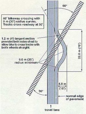
Bike lane or shoulder crossing railroad tracks.
Angle of Crossing: The risk is kept to a minimum where the bikeway crosses the tracks at a 90° angle. If the skew angle is less than 45°, special attention should be given to the bikeway alignment to improve the angle of the approach, preferably to 60° or greater, so cyclists can avoid catching their wheels in the flange and losing their balance.
Flange Opening: The open flange area between the rail and the roadway surface can cause problems for cyclists, since it can catch a bicycle wheel, causing the rider to fall. Flange width must be kept to a minimum. Note: The combination of smoothness, angle, and flange opening create conditions that affect cyclists. By improving smoothness and flange opening, the angle becomes less critical.
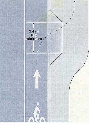 Ramp provides access to sidewalk. |
These can help cyclists if the bridge sidewalks are wide enough for bicycle use (minimum 1.2 meters [4 feet]). They should be provided where motor vehicle traffic volumes and speeds are high, the bridge is fairly long, and the outside traffic lanes or shoulders on the ridge are narrow.
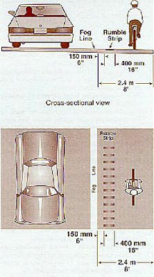
Rumble Strips Rumble strips are provided to alert motorists that they are wandering off the travel lanes onto the shoulder. They are most common on long sections of straight freeways in rural settings, but are also used on sections of two-lane undivided highways.
Bicycles are allowed on some freeways and expressways and on most primary and secondary roads. Many bicyclists prefer to ride on the shoulder, outside the travel lane and out of the truck and automobile traffic stream. One of bicyclists' main concerns about rumble strips is the ability to control the bicycle when the rider needs to travel across or along the rumble strip for such maneuvers as a left turn or to avoid debris or an obstacle on the paved shoulder. Travel to the right of the rumble strip is generally most beneficial for the bicyclist as long as that area is free of debris and obstacles and the travel path is wide enough to comfortably accommodate the bicycle. A newer rumble strip design is more bicyclefriendly: 400-millimeter (16-inch) grooves are cut into the shoulder, 150 millimeters (6 inches) from the fog line. On a 2.4-meter (8-foot) shoulder, this leaves 1.8 m (6 feet) of usable shoulder for bicyclists. Some highway agencies have instituted policies that prohibit the use of shoulder rumble strips on roads designated as bike routes or where there is insufficient remaining paved shoulder room to accommodate bicycle travel. Others evaluate the use of rumble strips on a case-by-case basis and often opt to install them only at locations with a history of run-off-road crashes.
Several options are being considered to address the concerns of the bicycle traveler. The selection of a particular shoulder rumble strip design or revisions to current designs may provide part of the solution. For example, milled shoulder rumble strips are narrow and usually require less space on the shoulder than other types of strips. The narrower width of the strip allows more shoulder room for the bicyclist to maneuver on the right side of the shoulder.
Other designs being used and investigated use a skip pattern of rumble strip that provides a smoother travel path throughout portions of the strip for bicyclists to move to the left when needed. Also, some highway agencies are providing an aid to cyclists and all travelers in general by posting roadside signs, such as RUMBLE STRIPS AHEAD, alerting the traveler to the presence of the shoulder rumble strip.
Bicycle-friendly rumble strip.
Choose a local street that would be a good candidate for a bicycle boulevard. The street segment should be several blocks in length, and should include at least one crossing of a major arterial. Prepare a conceptual design plan for the street segment, showing the location of signing, traffic signals, onstreet parking, and traffic-calming features. Your design should be shown in plan view, and should be accompanied by a narrative explaining the purpose of special design features.
Text and graphics for this section were derived from the following sources:
American Association of State Highway and Transportation Officials, Guide for the Development of Bicycle Facilities (Review Draft), 1997.
Federal Highway Administration Website, Office of Highway Safety, Rumble Strip Web page, 1999.
Oregon Department of Transportation, Oregon Bicycle and Pedestrian Plan, 1995.
For more information on this topic, refer to:
USDOT, Manual on Uniform Traffic Control Devices (latest version)
| < Previous | Table of Content | Next > |

