U.S. Department of Transportation
Federal Highway Administration
1200 New Jersey Avenue, SE
Washington, DC 20590
202-366-4000
As with any project development process, practitioners designing a Road Diet should take into account the principles and practices that guide design decisions, including geometric design and operational design.
Geometric design includes identifying details of the project in plan, profile, and cross section. It is necessary to apply the standard principles and practices of geometric design. Geometric designers are guided by standards and policies that include design criteria. The criteria serve as a guide to design and provide uniformity, but are not intended to be inflexible. Designers need flexibility to achieve context-specific needs and objectives. This is particularly true for Road Diet implementations. FHWA's Flexibility in Highway Design illustrates the different methods available to highway engineers and project managers to design roads that move people and goods in a safe, efficient, and reliable way while at the same time fully considering community values for the corridor and broader location.51 AASHTO's A Guide for Achieving Flexibility in Highway Design also shows how community and environmental issues can be integrated into decision-making throughout the project development process.52 Additional information about design flexibility pertaining to pedestrian and bicyclist facilities can be found in FHWA's August 2013 Bicycle and Pedestrian Facility Design Flexibility memo.53
The practice of designing roads geometrically is evolving towards more performance-based approaches to analysis, where the expected transportation outcomes of geometric design decisions are quantified and used to support informed design decisionmaking. Performance-based analysis complements the ideas of design flexibility, context sensitive design, and practical design. Performance-prediction tools, such as the Highway Safety Manual, Highway Capacity Manual and others quantify how geometric design decisions impact measures of user accessibility, mobility, quality of service, reliability, and safety. A framework for conducting performance-based analysis is provided in the final report for NCHRP 15-34A, Performance-Based Analysis of Geometric Design of Highways and Streets.
The functional classification system described by FHWA's Functional Classification Guidelines and Updated Guidance for the Functional Classification of Highways often serves as a basis for establishing design criteria for a Road Diet project. AASHTO's Green Book, for example, includes chapters organized by functional classification, with arterials divided into freeway and non-freeway facilities (e.g., Chapter 5, Local Roads and Streets; Chapter 6, Collector Roads and Streets; Chapter 7, Rural and Urban Arterials; and Chapter 8, Freeways). Alternative road classifications also exist. These alternative classification systems guide designers towards establishing design criteria that are complimentary to location-specific context where the Road Diet is being implemented. For example, the Smart Transportation Guidebook,54 jointly published by the Pennsylvania and New Jersey DOTs, more explicitly considers project setting by defining seven context areas from least to most developed:
| Characteristic | Rural | Suburban Neighborhood | Suburban Corridor | Suburban Center | Town/Village Neighborhood | Town Center | Urban Core |
|---|---|---|---|---|---|---|---|
| Density Units (DU)a per acre (ac) | 1 DU/20 acb | 1-8 DU/ac | 2-30 DU/ac | 3-20 DU/ac | 4-30 DU/ac | 8-50 DU/ac | 16-75 DU/ac |
| Building Coverage | NAc | < 20% | 20-35% | 35-45% | 35-50% | 50-70% | 70-100% |
| Lot Size/Area in square feet (sf) | 20 ac | 5,000 - 80,000 sf | 20,000- 200,000 sf | 25,000-100,000 sf | 2,000-12,000 sf | 2,000-20,000 sf | 25,000-100,000 sf |
| Lot Frontaged | NA | 50 -200 ft. | 100-500 ft. | 100-300 ft. | 18-50 ft. | 25-200 ft. | 100-300 ft. |
| Block Dimensions | NA | 400 ft. wide x variable length | 200 ft. wide x variable length | 300 ft. wide x variable length | 200 ft. wide x 400 ft. long | 200 ft. wide x 400 ft. long | 200 ft. wide x 400 ft. long |
| Max. Height | 1-3 stories | 1.5 -3 stories | 1 story retail; 3-5 story office | 2-5 stories | 2-5 stories | 1-3 stories | 3-60 stories |
| Min./Max. Setback | Varies | 20-80 ft. | 20-80 ft. | 20-80 ft. | 10-20 ft. | 0-20 ft. | 0-20 ft. |
|
a The guidebook does not define a density unit and may instead be referring to a dwelling unit; dwelling units per acre are used in the guidebook to define high-, medium-, and low-density areas. b acre c not applicable d The distance measured between points where side property lines meet road right-of-way lines |
|||||||
The guidebook includes a set of quantifiable characteristics for each of the seven context areas and a recommendation that the land use context be identified based on this information. The quantifiable characteristics are summarized in Table 4. Land use contexts are broadly defined for road segments greater than 600 feet in length due to practical limitations on the frequency of changing the roadway typical section over a short stretch of road.
Once the context area of the Road Diet is defined, the Smart Transportation Guidebook includes a "matrix of design values" with design criteria as rows and land use contexts as columns for five different roadway types: 1) regional arterial, 2) community arterial, 3) community collector, 4) neighborhood collector, and 5) local road. An example for regional arterials is shown in Table 5. This roadway typology is different than the existing functional classification system outlined by FHWA and was proposed to capture the actual role of the roadway in the surrounding community. Access, mobility, and speed are considered on the road segment of interest as opposed to using only one functional classification for an entire highway. This alternative approach to classifying the context area of the Road Diet beyond more traditional functional classification will encourage design criteria that are consistent with broader project surroundings and area characteristics.
Design controls are fixed factors outside of the design process, but may dictate the result. Examples include vehicles, environment, traffic (non-motorized and motorized), and others, including applicable financial and regulatory influences. Candidate Road Diet locations may be identified due to the characteristics of these design controls at that location (see, for example, discussion in Chapter 3 of this guidebook). More broadly, designers should understand the intended project outcomes as well as the characteristics of the stakeholders that the Road Diet implementation is intended to serve. A thorough discussion of design controls appears in AASHTO's A Policy on Geometric Design of Highways and Streets.55 This section summarizes some key points.
| Regional Arterial | Rural | Suburban Neighborhood | Suburban Corridor | Suburban Center | Town/Village Neighborhood | Town/Village Center | Urban Core | |
|---|---|---|---|---|---|---|---|---|
| Roadway | Lane Width | 11' to 12' | 11' to 12' (14' to 15' outside lane if no shoulder or bike lane) | 11' to 12' (14' to 15' outside lane if no shoulder or bike lane) | 11' to 12' (14' outside lane if no shoulder or bike lane) | 10' to 12' (14' outside lane if not shoulder or bike lane) | 10' to 12' (14' outside lane if not shoulder or bike lane) | 10' to 12' (14' outside lane if not shoulder or bike lane) |
| Paved Shoulder Width | 8' to 10' | 8' to 10' | 8' to 12' | 4' to 6' (if no parking or bike lane) | 4' to 6' (if no parking or bike lane) | 4' to 6' (if no parking or bike lane) | 4' to 6' (if no parking or bike lane) | |
| Parking Lane | NA | NA | NA | 8' parallel | 8' parallel; see 7.2 for angled | 8' parallel; see 7.2 for angled | 8' parallel | |
| Bike Lane | NA | 5' to 6' (if no shoulder) | 6' (if no shoulder) | 5' to 6' | 5' to 6' | 5' to 6' | 5' to 6' | |
| Curb Return | 30 ' to 50' | 25' to 35' | 30' to 50' | 25' to 50' | 15' to 40' | 15' to 40' | 15' to 40' | |
| Number of Travel Lanes | 2 to 6 | 2 to 6 | 4 to 6 | 4 to 6 | 2 to 4 | 2 to 4 | 2 to 6 | |
| Roadside | Clear Sidewalk Width | NA | 5' | 5' to 6' | 5' to 6' | 6' to 8' | 6' to 10' | 6' to 12' |
| Buffer | NA | 6'+ | 6' to 10' | 4' to 6' | 4' to 6' | 4' to 6' | 4' to 6' | |
| Shy Distance | NA | NA | NA | 0' to 2' | 0' to 2' | 2' | 2' | |
| Total Sidewalk Width | NA | 5' | 5' to 6' | 9' to 14' | 10' to 16' | 12' to 18' | 12' to 20' | |
| Speed | Desired Operating Speed (mph) | 45-55 | 35-40 | 35-55 | 30-35 | 30-35 | 30-35 | 30-35 |
Drivers. Considering driver performance remains as critical for Road Diet design as for any other facility type. Road Diet designs should be compatible with driver capabilities and limitations and should be laid out to meet driver expectations. Designers should consider positive guidance to all road users (e.g., pavement marking, signing, delineation) to make the desired path clear. Driver considerations in highway design are covered in FHWA's A User's Guide to Positive Guidance and NCHRP's Human Factors Guidelines for Road Systems.57, 58
Road Diets can be particularly beneficial for older drivers who have slower reaction times and reflexes. According to FHWA's Public Roads, "The safety potential of conversion to a three-lane cross-section (also called Road Diets) was so compelling to Iowa DOT officials, based on studies done in Minnesota, Montana, and Washington, that Iowa DOT made this project type a staple of its agency's older driver program at the program's inception in 1999."59 Additional guidance on highway design, operational, and traffic engineering features, including Road Diets, for older road users is available in the FHWA Handbook for Designing Roadways for the Aging Population.
Non-motorized Users. When appropriately applied, Road Diets have generated benefits to users of all modes of transportation, including bicyclists, pedestrians, and motorists. Specific benefits to non-motorized users were covered previously. Pedestrian volumes and characteristics will influence the design of sidewalks, crosswalks, traffic control features, curb cuts, bus stops, and other locations where pedestrian traffic is expected. Guidance for designing roadways to accommodate pedestrians as well as designing pedestrian facilities themselves is contained in AASHTO's Guide for the Planning, Design, and Operation of Pedestrian Facilities. Road Diets also provide the opportunity to add bicycle lanes to roads on which bicyclists previously shared lanes with motor vehicles or navigated between travel lanes and the edge of pavement. Bicycle dimensions and operating characteristics influence the design of bicycle facilities, as identified in AASHTO's Guide for the Development of Bicycle Facilities.60Furthermore, the FHWA supports the consideration of additional design options found in the National Association of City Transportation Officials (NACTO) Urban Bikeway Design Guide and the ITE Designing Walkable Urban Thoroughfares manuals in addition to the AASHTO bicycle and pedestrian guides to aid in designing safe and comfortable bicycle and pedestrian facilities. These resources expand practitioners' options in how to accommodate these users.61
Speed. Speed is one of the most important and complex factors that both influences and is influenced by road geometrics. Drivers select travel speeds based on their perceptions of the road. Sometimes geometric design criteria can lead to operating speeds that are higher than design speeds for design speeds less than 55 mph. Road Diets have the potential to reduce operating speed differentials, but tend to have a modest effect on the average operating speed of the corridor (i.e., about 3 to 5 mph). The reduction in the number of through lanes can affect the speed differential by removing the ability to pass slower moving vehicles. Changes in the road cross section may also influence drivers' perceptions of appropriate free-flow speeds. Geometric designers should seek to achieve speed harmony, defined in FHWA's Speed Concepts: Informational Guide, as the condition that results when:
Principal elements of geometric design include sight distance, horizontal alignment, superelevation, and vertical alignment. Conversions do not generally involve significant changes in sight distance and alignment, but these characteristics may require additional assessment due to changes in cross-section allocation and use.
Sight Distance. Drivers need sufficient sight distance to control the operation of their vehicles and avoid striking unexpected objects in the travel way. Stopping sight distance, decision sight distance, and intersection sight distance are most relevant to Road Diet locations. Stopping sight distance, or the distance required for a vehicle to stop before reaching a stationary object in its path, should be available at all points on the road. Decision sight distance should be provided at complex locations where drivers must make instantaneous decisions, where information is difficult to perceive, or where unexpected maneuvers are needed. Significant changes in alignment are not expected during Road Diet conversions, so changes in sight distance due to the alignment design are likely to be insignificant. Changes in vehicle position due to the cross section changes may have some impact on horizontal sight distance (i.e., available sight distance while traversing a horizontal curve, limited by sight obstructions on the inside of the curve). Critical sight distance analysis for Road Diet conversions will include pedestrian crossings, transit stops, and locations where on-street parked cars serve as possible sight obstructions.
Road Diets can provide sight distance improvements for mid-block, left-turning drivers at entrances due to the conversion of the four-lane, undivided roadway to a TWLTL. Drivers in a four-lane, undivided situation experience negative offset with opposing traffic, which can block their view. In a TWLTL this negative offset is removed, so drivers making left turns have improved sight distance to make a safe movement.
Grade. Designers select grades to provide uniform operation and enable operating speeds near the design speed of the roadways. Grades at locations with Road Diet conversions will likely already be determined. Maximum grades typically range from 5 to 12 percent and are determined based on functional classification, design speed, and terrain. The effects of grades on truck speeds are much greater than effects on passenger cars. Given that Road Diet implementation has reduced the cross section to one through lane in each direction, design vehicle performance will have a greater impact on overall vehicle operations and the grade and critical length of grade may become more influential features impacting performance than they were for the four-lane undivided cross section.
Horizontal Curvature and Superelevation. Road Diet conversions are not likely to involve any significant changes in horizontal curvature and superelevation. Basic design speed, side friction, and superelevation relationships apply, and guidance is available in AASHTO's A Policy on Geometric Design of Highways and Streets.
Access Management. Given the operational change that will occur through a lane reduction in each direction of travel as well as the addition of a TWLTL, access management should be analyzed during the Road Diet conversion. Driveways are, in effect, low-volume intersections.
The re-analysis should consider:
FHWA provides additional resources related to access management, including Access Management in the Vicinity of Intersections Technical Summary.63
There are a number of cross sectional elements to consider for a Road Diet conversion. For example, practitioners need to consider the commonly accepted range of lane widths, but the design must also fit within the existing curb-to-curb distance using flexibility in commonly used design manuals. The sections below discuss individual cross sectional design criteria.
Lane widths. Lane width influences operations, safety, quality of service, and the security felt by road users. Widths of 10 to 12 feet are typically used in practice. Auxiliary lanes (i.e., turn lanes) at intersections are often the same width as through lanes, and seldom less than 10 feet. The width of the TWLT lane provided as part of a lane width conversion typically ranges from 10 to 16 feet. The width for a bus lane along these roadways is usually 11 to 15 feet.64
Median. A median is defined as the area between opposing travel lanes. Its main purpose is to separate opposing traffic. Design width depends upon the type of roadway and its location. On urban area arterial streets, a TWLTL can effectively accommodate left-turning traffic. When a flush median is used, practitioners should expect crossing and turning movements in and around the median.65
Pedestrian Refuge Island. A pedestrian refuge island both shortens the time and distance that a pedestrian is exposed to moving traffic while also simplifying the crossing. It provides a protected space in the roadway, allowing the pedestrian to make the crossing in two stages if necessary. In this situation, the pedestrian only has to focus on finding a gap in one direction of travel at a time. The refuge island should be a minimum of 6 feet wide, in the direction of pedestrian travel, with 8 to 10 feet preferred. The island should include detectable warning tiles where it meets the roadway. On streets with a TWLTL, pedestrian refuge islands can use the turn lane space where turns are prohibited, such as at an intersection with a one-way street, or can be installed adjacent to the TWLTL where space allows.
Cross Slope. Generally, the crown or high point of the converted cross section is located in the center of the TWLTL, with the slope of the pavement the same as the adjacent through lanes. Typical cross slopes are 1.5 to 2 percent, and may be as high as 2.5 percent in areas of intense rainfall. Additional information on minimum accessibility standards is available in the Draft Public Rights of Way Accessibility Guidelines (PROWAG).
Shoulders. Shoulders are the portions of the roadway adjacent to the traveled way. In most Road Diet applications, curb-to- curb widths and the desire to allocate the space to traffic, bicycle lanes, and parking limit ability to provide shoulders. Painted buffers are sometimes provided between the traveled way and bicycle lanes, and those buffers offer some similar advantages as shoulders. Chapter 3 of this guide includes marking examples for undesignated pavement widths, including painted buffers between the traveled way and bicycle lanes.Curbs. Curbs may already be present at the Road Diet conversion location, as they are commonly used in lower speed urban and suburban areas. Curbs have multiple functions, including drainage, delineation, right-of-way reduction, and delineation of pedestrian walkways.
Drainage. Drainage facilities include bridges, culverts, channels, curbs, gutters, and various types of drains. Road Diet conversions usually do not require significant changes in drainage design, as pavement widths and slopes remain relatively unchanged. AASHTO's Highway Drainage Guidelines and Model Drainage Manual are two key drainage references used by designers.66, 67
Pedestrian Facilities. Road Diet conversions will not typically involve changes to the pedestrian sidewalk facilities outside the curb. They do benefit pedestrian performance in a number of other ways that have been noted throughout this document. For example, Road Diets may introduce the opportunity for on-street parking, creating a buffer between pedestrians and moving vehicles. The change in the roadway cross section also results in fewer travel lanes for pedestrians to cross. Separating opposing directions of travel by a TWLTL can provide space for a refuge island at pedestrian crossing locations, if necessary. Adding dedicated bike lanes to a roadway can positively impact pedestrians by getting bicyclists off the sidewalk and into the street. For any changes to the pedestrian facilities, including the addition of pedestrian refuge islands, designers can reference AASHTO's Guide for the Planning, Design, and Operation of Pedestrian Facilities and the Public Rights-of-Way Accessibility Guidelines.68, 69Figure 19. Bicycle Lane on Rural 3-Lane Section, Lawyers Road, Reston, VA
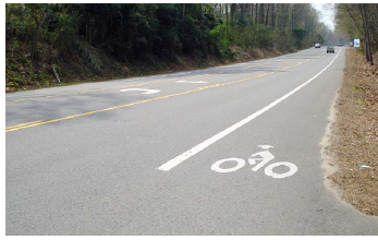
Photo Credit: Virginia DOT
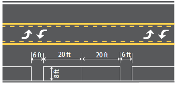
Bicycle Facilities. Road Diets allow the addition or expansion of bicycle facilities. On roads where bicyclists previously shared lanes with motor vehicles or navigated between travel lanes and the edge of pavement, the opportunity to provide a separate facility arises. Where bicycle lanes already existed, the Road Diet presents an opportunity to provide even more separation by adding a painted buffer or a physical separation using parked cars, bollards, or curb. Bicycle lane widths should be determined based on context and anticipated use, including the speed, volume, and types of vehicles in adjacent lanes. AASHTO's Guide for the Development of Bicycle Facilities covers the design of these bicycle lanes.70 Under typical circumstances, the width of a one-way bicycle lane is 5 feet. A minimum width of 4 feet can be used on roadways with no curb and gutter. Wider bicycle lanes should be considered when feasible, and especially at locations with narrower parking lanes (e.g., 7 feet), high bicycle volumes, and higher speed roadways or roadways with a significant number of larger vehicles. When 7 feet or more is available for the bicycle facility, a buffered or protected bike facility should be considered. Typical bicycle lane cross sections are illustrated in Figure 20. The presence of a bicycle lane influences the recommended design of on-street parking accommodations as well.
Figure 20. Typical Bike Lane Cross Sections

(Adapted from AASHTO)
On-street Parking. Road Diets provide the opportunity for parallel or diagonal on-street parking. The desirable minimum width of a parallel parking lane is 8 feet, as most vehicles will occupy approximately 7 feet of actual street space when parallel parked. A parking lane width of 10 to 12 feet may be desirable to provide additional clearance from the traveled way and accommodate transit operations, though some jurisdictions have used parking lane widths as narrow as 7 feet, particularly where only passenger cars need to be accommodated in the parking lane.71 As noted, parallel parking lanes may also be separated from bicycle lanes by an optional solid white line. Where parallel parking and bike lanes are present, but a parking lane line or stall markings are not used, the recommended width of the shared bicycle and parking lane is 13 feet. In addition, practitioners could consider "paired parking" to reduce conflicts and delays with vehicle parking (see Figure 21).
Figure 21. Paired Parking Illustration
The treatment of a parking lane approaching an intersection requires special consideration. If the lane is carried up to the intersection, right-turning vehicles may use it in the absence of parked vehicles, potentially leading to undesirable operations. However, keeping a parking lane can increase the effective corner radius for large right-turning vehicles. Other options include using a parking lane transition (i.e., a "bulb out," as shown in Figure 22) or prohibiting parking a certain distance from the intersection.
Figure 22. Example Parking Lane Transition at Intersection
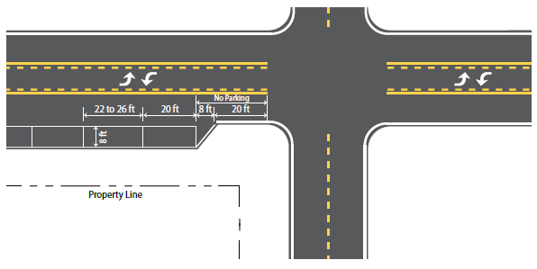
(Adapted from AASHTO, 2011)
Bus Turnouts. One potential concern with a Road Diet installation is that stopped buses in the now-singular through lane block all downstream vehicles while loading and unloading. The paved width available with the installation of a Road Diet provides space for potential accommodations for bus operations (e.g., stopping, loading, unloading) away from the traveled way by using a turnout. Bus stop locations should provide about 50 feet in length for each bus. In some cases, there may be room to provide deceleration and entry tapers using a combination of pavement markings. A taper of about 5:1, longitudinal to transverse, is a desirable minimum. When the stop is on the near or far side of an intersection, the width of the cross street is generally adequate for merging back into traffic or diverging to the bus stop, respectively.
Keep in mind, however, that most transit operators prefer in-lane stops versus turn-outs due to the difficulties of through lane ingress from the turn-out.
Bus stops located at the near side or far side of intersections provide pedestrian access from both sides of the street and connections to intersecting bus routes. The presence of curb extensions also facilitates passenger access. Additional discussion can be found in Transit Cooperative Research Program (TCRP) Report 19, Guidelines for the Location and Design of Bus Stops, ITE's Designing Walkable Urban Thoroughfares: A Context Sensitive Approach, and agency guidance on bus stop placement and design. Guidelines for the Location and Design of Bus Stops provides additional information on the location and design of bus stops.72
Cross Section Transitions. The starting point and ending point of a Road Diet conversion may require a transition from or to a different cross section. The design of these locations is typically a function of the width of the lane to be dropped and the posted or design speed at the lane drop locations. The Manual on Uniform Traffic Control Devices provides additional detail. Taper ratios for lane additions are typically around 15:1, longitudinal to transverse.
Another important decision with respect to the cross section transitions that are part of the Road Diet is the location of the transitions. Overall, continuity of the two through lanes and one TWLTL lane is important, and transition points should occur at locations where the only decision a driver needs to make is related to the lane drop or addition. The objective when selecting a transition point location is to minimize the complexity of the transition area and the number of decisions or potential conflicts that could occur while a driver is merging or diverging. For this reason, transitions should not occur at or near intersections or major driveways (within their influence area). The Iowa guidelines further propose that Road Diet conversions should be questioned if additional through lanes are needed at the signalized intersections along the corridor. This type of transition may have a negative result on safety and lessen the benefits of the Road Diet conversion.
Some transitions are less complicated than others. For example, the transition from a two-lane undivided roadway to a three-lane roadway is relatively simple and straightforward (see Figure 23). The general concerns noted above about the selection of transition point locations should still be taken into account. The transition from a four-lane undivided to a three-lane roadway requires dropping the outside through lanes in advance of the complete cross section conversion. This type of transition requires closer attention and involves the potential for through-vehicle conflicts. Overall, the lane drop and the introduction of the TWLTL should be installed in close proximity to each other. The transition from a five-lane roadway to a three-lane roadway is a similar situation but the introduction of a new TWLTL is not necessary. The same issues will also be encountered when transitioning from a three-lane roadway to some other type of cross section.
Figure 23. Transition from 3-lane to 2-lane Cross Section, Oak Street, Merrifield, VA
Photo Credit: Virginia DOT
Overall, it is also important to look at the roadway cross sections near the end of the "project limits" for a Road Diet conversion. The overall objective is to minimize the number of transitions within a short distance. In other words, it may sometimes be more appropriate to extend the "project limits" to avoid this situation. Through lanes should also not be dropped as a turn lane at an intersection. This type of lane drop is not good design. It will often "catch" vehicles that want to continue through the intersection and drivers may then make inappropriate maneuvers.
Basic principles of intersection design apply to intersections bordering or within the Road Diet area. Given the cross sectional change during Road Diet implementation, practitioners should perform a new operational analysis at each intersection (see Chapter 5). New lane arrangements and signal phasing are also possibilities, as discussed in other sections of this guide. The remainder of this section will include an overview of some design considerations for intersections bordering or within the Road Diet area with references to other documents as appropriate.
Alignment and Profile of Intersection Approaches. Intersecting roads should meet at or nearly at right angles and the grades should be as flat as possible. These characteristics are likely predetermined at locations experiencing a Road Diet conversion, but designers should be aware of their negative effects on capacity, sight distance, and safety and look for opportunities to implement possible countermeasures.
Intersection Sight Distance. Check intersection sight distance at each intersection bordering or within the Road Diet area. Drivers of approaching vehicles should have an unobstructed view of the entire intersection as well as sufficient lengths along the intersecting road to allow the observance and avoidance of potential conflicts with other vehicles. Drivers of stopped vehicles should also have a sufficient view of the intersecting highway to decide when to enter (with a left or right turn) or cross it. These design objectives are achieved by providing sight triangles. Approach and departure sight triangles are discussed in detail in AASHTO's A Policy on Geometric Design of Highways and Streets. It is likely that the sight distance needs for minor streets intersecting the new three-lane cross section decrease following the Road Diet conversion due to entering vehicles needing to cross fewer lanes. Other sections of this document also note how available sight distance for vehicles turning left from the TWLTL is likely greater than that along a four-lane, undivided cross section.
Several states have enacted traffic laws that define and govern driver use of TWLTLs. The provisions of these laws vary widely, and most States do not appear to have enacted such traffic laws. Based on an Internet search of key terms related to "two way left turn lanes" and "center turn lanes", the research team identified laws in 18 States that define and govern driver use of TWLTLs. Six types of laws were identified and are labeled "a" through "g" below. More than half of the 18 States specify the following:
(a) Where a TWLTL is provided, motorists may not turn left from any other lane
(b) Vehicle shall not be driven in a TWLTL except when preparing for or making a left turn/U-turn
Ten States have enacted laws that (c) limit the distance a motorist may travel in a TWLTL – either a specified maximum distance, or the shortest distance practicable and safe, as summarized in Table 6:
| Distance | State |
|---|---|
| 150 Feet | Virginia |
| 200 Feet | California, Louisiana, Oklahoma, Rhode Island |
| 300 Feet | Georgia, Washington |
| 500 Feet | Missouri |
| Shortest practicable distance/safe distance | Maryland, Tennessee |
Four States have enacted laws that (d) stipulate that TWLTLs shall not be used for passing/overtaking another vehicle.
Tennessee is unique in passing laws that specify the following:
(e) When vehicle enters turn lane, no other vehicle proceeding in opposite direction shall enter that turn lane if that entrance would prohibit the vehicle already in the lane from making the intended turn
(f) When vehicles enter the turn lane proceeding in opposite directions, the first vehicle to enter the lane shall have the right-of-way
Arkansas is the only State to enact the following provision:
(g) It is permissible for vehicle making a left turn from an intersecting street or driveway to utilize TWLTL to gain access to or to merge into the traffic lanes, except not permissible to use the center left-turn lane as an acceleration lane
In terms of guidelines, the six types of TWLTL laws identified in the 18 States provide reasonable instructions to drivers and can help promote safe driver actions on corridors with TWLTLs. Although it is unclear what factors or data the States used to determine the maximum allowable travel distance in TWLTL, limiting the distance drivers are permitted to travel in TWLTLs – if not overly restrictive – can enhance safety by reducing opportunities for opposing-direction crashes, as well as crashes involving pedestrians that use TWLTLs as a crossing refuge. One concern about stipulating short maximum travel distances is the risk of failing to account for the need for drivers to decelerate from highway speeds when entering TWLTLs.
Regardless of the specific TWLTL laws enacted, it is suggested that State driver manuals define proper use of TWLTLs, including information regarding laws that govern TWLTLs.
Right Turn Lanes. With the Road Diet conversion, it may be possible and desirable to provide an exclusive lane for right-turning traffic. The delay impact of vehicles turning right should be evaluated and a decision made about whether a right-turn lane is needed. Some cases may require additional right-of-way or pavement width. The volume of turning vehicles and the types of vehicles to be accommodated govern the widths of turning roadways. Always consider pedestrian safety when deciding whether to add a right-turn lane at intersections. If the right-turn lane is free flow, yield controlled, or if right turn on red is allowed at the intersection, then pedestrians will be affected.
Turning radii are functions of turning speed and vehicle type. There are three types of designs for right-turning roadways at intersections: 1) minimum edge of traveled way, 2) design with a corner triangular island, and 3) free-flow design using a simple radius or compound radii. A detailed discussion is provided in AASHTO's A Policy on Geometric Design of Highways and Streets. Where pedestrians and bicyclists are present and trucks are only occasionally present, it may be desirable to use smaller turning radii to decrease the intersection area and reduce turning speeds.
However, the designer should analyze likely turning paths and encroachments when a larger vehicle does use the intersection and its effect on traffic operations and safety. Depending on truck volumes, the typical size of trucks using the intersection, and nearby truck traffic generators, practitioners should consider larger radii to accommodate these road users.
Driveway geometrics are also the focus of NCHRP 659 Guide for the Geometric Design of Driveways.73 The inside and outside turning radius of design vehicles should also be considered when the corridor being converted is not straight (e.g., the main designated route that is converted is two legs of an intersection that are at right angles to each other). Pavement marking and corner radii should be designed in combination to serve the left- and right-turn movement of the design vehicle at these locations.
Roundabouts. A single-lane roundabout can be a good fit geometrically as part of a Road Diet installation. A roundabout will provide additional opportunities for improved safety by eliminating most angle and head-on crash types, and by reducing intersection operating speeds.
Care should be taken, however, regarding public reaction to installing a Road Diet and roundabout(s) on the same corridor. Depending on public sentiment, adding a roundabout to the discussion could create additional concerns from nearby residents, business owners, and road users if they are not familiar with navigating roundabouts.
Bicycle Design Considerations. Where the Road Diet includes on-street bicycle lanes, intersection designs should be modified accordingly. The bicycle facility should be carried up to and through the intersection. Where right- turn lanes are added, lane markings will be needed to channelize and separate bicycles from right-turning vehicles. Additional considerations include provisions for left-turn bicycle movements, use of bicycle boxes, and bicycle-specific traffic signals.
Details related to these intersection design features are contained in AASHTO's Guide for the Development of Bicycle Facilities and NACTO Urban Bikeway Design Guide.
Curb Ramp Design. Pedestrian facilities must also accommodate all users, including those with mobility, vision, cognitive and other impairments. Curb ramps must land within the width of the pedestrian street crossing they serve, and wholly outside the parallel vehicle travel lane. A distinct curb ramp should be provided for each crossing direction. Where possible, aligning the curb ramp with the direction of the crosswalk is preferred. Keeping the curb radius small, including a buffer space between the sidewalk and the curb, and adding curb extensions are all strategies that aid in being able to achieve two distinct ramps at a corner that are compliant with the design requirements per the Americans with Disabilities Act (ADA). Additional guidance on curb ramp design is available from the Draft Public Rights-of-Way Accessibility Guidelines. While these guidelines are still in draft form, they and their successors are considered to be the leading guidance on the subject.
Curb Extensions. On roadways with on-street parking, curb extensions at intersections can be added to shorten pedestrian crossing distances and make the pedestrian waiting at the corner more visible to drivers. Similarly, it gives the pedestrian a better view of oncoming traffic without having to step into the roadway. Curb extensions should only be used where on-street parking is permitted and should be slightly narrower than the parking lane, so that the extension is not bumping out into the traveled way for either bicyclists or motor vehicles.
Other Pedestrian Design Considerations. Intersection design should facilitate safe and convenient crossings. Curb radii should be kept as low as practical in order to slow vehicle speeds as they turn. The radius will also impact the crossing distance, making it shorter as the radii get smaller. The addition of on-street parking or bicycle lanes may enable a smaller curb radii at intersections as the effective radius of the vehicle path gets larger with the separation from the curb that the parking and bike lanes provide. Additional discussion is provided in AASHTO's Guide for the Planning, Design, and Operation of Pedestrian Facilities and FHWA's Maintaining Pedestrian Facilities.
The success of a Road Diet cross-section conversion is often based on whether the operation and safety of the roadway are maintained or improved for all road users. The operational impacts of a Road Diet conversion, as noted in previous chapters, can be relatively small if properly implemented in an appropriate location (e.g., a four-lane undivided roadway that already operates similar to a "de facto" three-lane roadway). Past experiences with this type of conversion, however, have also shown that there a number of decisions that users of these guidelines may want to consider closely before the design and implementation of a Road Diet conversion in order to increase its potential success.
This section includes a brief description of some of the factors to consider in decisions related to:
The list above should not be considered exhaustive. Each corridor will have its own unique issues and needs. Engineering judgment and expertise need to be applied to each corridor design in order to respond to these situations. In addition, not all of the situations listed above are applicable to every corridor. The objective of this section, however, is to discuss the subjects above; note what has been learned in the past about how or why they need to be addressed; and, if applicable, identify some of the resources that could be used to respond appropriately. This section assumes that the Road Diet conversion option has already been selected through the input and involvement of all road users, adjacent land owners, and the appropriate public agencies and jurisdictions.
Road Diet conversions typically require the reallocation of the existing curb-to-curb or pavement-edge-to-pavement-edge distance, and the decision of how to allocate these distances can be complex. In fact, in many cases the Road Diet conversion option is selected because of its minimal impacts on the general "footprint" of the roadway and because there is typically no need for right-of-way acquisition (although spot locations of "widening" may occur). The reallocation of an existing cross section should take into account the objectives for the existing corridor as well as the needs of the road users it serves. In addition, practitioners must choose the type and width of each "lane." The lane types along three lane roadways have included, but not been limited to, through lanes, TWLTLs, bike lanes, transit lanes, and parking lanes. Each corridor that is being converted should be individually evaluated and designed. Before installation, the TWLTL was used illegally for loading due to lack of other available space. Seattle DOT added "Load Zones" on Dexter Avenue in Seattle, Washington, to address delivery truck needs.
In NCHRP Report 282, the authors suggest that there are situations with high left-turn volumes and lower through volumes in which conversion of a four-lane, undivided roadway to a three-lane cross section might be accomplished without lowering "operational efficiency."74 In NCHRP Report 330 the authors suggest an eight-step process to select curb-to-curb cross section design alternatives.75 Both documents discuss the advantages and disadvantages of different cross-section designs.
In some cases, pedestrians crossing a three-lane (or five-lane) roadway may use the TWLTL as an unofficial refuge area, which may result in conflicts with motorists who do not expect to see pedestrians in that travel lane. This issue can be mitigated with pedestrian refuge islands. Pedestrian refuge islands should be used with caution, and care should be taken with their design, because they introduce a potential obstacle for vehicles in the TWLTL.
Corner or midblock curb bulb outs can reduce the length of the pedestrian crossing, and this may also allow a reduction in signal timing to serve pedestrians. Care should be taken in the design of the bulb out. Bulb outs should not extend into the path of a bicyclist and, therefore, are best used in conjunction with on-street parking. Also consider the reduction in turning radius at intersections if a pedestrian bulb out is installed.
The addition of a pedestrian refuge island at an intersection may also result in the need for more pavement width. There are a number of other measures that can also be applied to improve the experience of crossing pedestrians. One reference that includes a discussion of several pedestrian crossing treatments at unsignalized locations is TCRP Report 112/NCHRP Report 562 Improving Pedestrian Safety at Unsignalized Crossings (a guideline for pedestrian crossing treatments is in the appendix).76 Another resource that may be of value is the AASHTO Guide for the Planning, Design, and Operation of Pedestrian Facilities.77 The FHWA webpage for Pedestrian and Bicycle Safety also includes many resources – including an article entitled Proven Countermeasures for Pedestrian Safety in the March/April 2012 issue of Public Roads.78
Re-evaluate traffic signal phasing and timing when converting a four-lane undivided roadway to three lanes. Perform an operational analysis to evaluate the acceptability of the potential impacts of the existing and proposed cross section and signalization on major and minor street vehicle and pedestrian delay and queue lengths. This evaluation should also consider the potential impact of heavy vehicles. In general, signal timing and phasing, along with the type and number of lanes on all intersection approaches, may need to be altered to minimize the operational impact of the Road Diet conversion. Specifically, mainline traffic may need additional green time due to the lane capacity reduction, especially during peak hours, to maintain mainline level of service. This could increase side-street delay during those time periods.
It is also important to adjust the positioning of the signal heads for a Road Diet conversion so the signal heads align with the new lane configuration, and there is a minimum of one signal head installed over each traffic lane. The reader is referred to the signalization information in the Manual on Uniform Traffic Control Devices (MUTCD), particularly Part 4, which focuses on highway traffic signals and includes a discussion of pedestrian controls. The signing needed for signalized locations is also contained in the MUTCD. Another document that may be of value to the readers is the FHWA Signalized Intersections Informational Guide. The FHWA intersection safety website also includes a number of resources.
Experience has indicated that it may not be appropriate to complete a Road Diet conversion when new signalization locations are needed along the same corridor. This is especially true if a Road Diet conversion is a new option within a jurisdiction. In general, it is important for the road users to understand what type of delays, if any, may be due to the Road Diet conversion. The source of additional delays is not clear when a Road Diet conversion is implemented along with new signalization location(s). Each corridor is unique, however, and the success of a Road Diet conversion is based on the objectives for each roadway. The two improvements might also be implemented separately (e.g., the signalization could be done before or after the Road Diet conversion).
Roundabouts can be considered as well. In some cases a mini-roundabout will fit within the existing right-of-way and footprint of the previously stop-controlled or signalized intersection. Roundabouts can provide operational improvements to the intersection by reducing queues and providing more consistent flow. Additional information is available in NCHRP Report 672, Roundabouts Informational Guide, 2nd Edition.
The signing and markings for a three-lane roadway should follow the requirements and suggestions in the MUTCD. Many of the parts in the current MUTCD apply to three-lane roadways (e.g., Parts 2, 3, 4, 9). These parts focus on signing (e.g., regulatory, warning, and guide), pavement markings (e.g., lane lines, edge lines, and the TWLTL), signals, bicycles, and pedestrians. It is necessary to provide proper pavement markings and signing for, among other things, the TWLTL, right-turn lanes, pedestrian crossings, and refuge islands.
Pavement markings can also be used to properly position both stopped and turning vehicles so they can safely make turning maneuvers. The proper positioning (e.g., at a stop line) and turning radius of the design vehicle should be considered. Edge lines and/or parking space pavement markings may also sometimes be used to position through vehicles. Finally, if a Road Diet conversion only involves the re-marking of lane lines along an existing roadway cross section, it is extremely important that the old pavement markings are completely removed. More than one Road Diet conversion has resulted in unintended consequences and driver confusion because "ghost markings" (remnants of paint or other material) remained after implementation.
Intersection design guidance may also be found in the AASHTO Green Book and local or State roadway design guidance documents. The guidance contained in these documents should be followed when designing a three-lane roadway. Agencies considering a Road Diet may want to consider several intersection design elements, including traffic signalization, corner radii, and offset intersections.
Traffic Signalization. The signalization discussion in this chapter noted that timing, phasing, and approach lane arrangements may need to be adjusted with a Road Diet conversion. Minor street volumes are a critical input to this activity. More generally, the potential impacts of the conversion on traffic entering and exiting all minor streets and driveways need to be closely evaluated. The delay and queuing changes that may occur due to changes in signalization timing and phasing, and the availability of adequate gaps for minor street or driveway traffic (at unsignalized locations), should be well understood. Practitioners should quantify and compare any additional delays and queues to what is considered acceptable along the corridor of interest. The delay, safety, and through-vehicle impacts of vehicles backing on to the converted roadway should also be discussed.
Corner Radii. Corner radii and right-turn lanes are both part of intersection design. Right-turn lanes may need to be added along three-lane roadways at intersections and major driveways. Evaluate the delay impact of vehicles turning right and decide if a right-turn lane is needed. Some cases may require additional right-of-way or pavement width. Practitioners should consider the radii or turning radius of the design vehicle at each corridor intersection and driveway. The AASHTO Green Book includes information about the proper design of turn lanes and corner radii. Driveway geometrics are also the focus of NCHRP 659, Guide for the Geometric Design of Driveways.79 The inside and outside turning radius of design vehicles should also be considered when the corridor being converted is not straight (e.g., the main designated route that is converted is two legs of an intersection that are at right angles to each other). Design pavement markings and corner radii in combination to serve the left- and right-turn movement of the design vehicle at these locations.
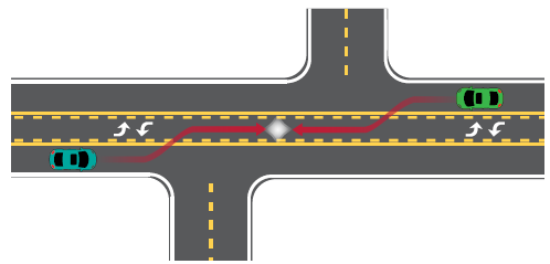
Offset Intersections and Driveways. Lastly, it is important to understand the impact of offset intersections and high-volume driveways on turning and through traffic. Operational and safety concerns may be introduced if there is a significant amount of "through" traffic on an offset minor street or major driveways. If the offset is oriented so that the minor street or driveway "through" vehicles turn right onto the main roadway, there is a greater possibility that opposing vehicles may want to travel in the TWLTL for an intersection or driveway offset distance. This situation occurs when one of the minor street vehicles entering the mainline may stop in the TWLTL and negatively impact other vehicles or make another unsafe maneuver.80
Figure 24. Offset Driveways Causing Conflict Points in the TWLTL
Source: FHWA-SA-10-002

