U.S. Department of Transportation
Federal Highway Administration
1200 New Jersey Avenue, SE
Washington, DC 20590
202-366-4000
| < Previous | Table of Contents | Next > |
There are several traffic control devices road agencies can and, in many situations, should consider installing at a horizontal curve, especially curves that data or experience identify as a safety problem location. These devices are considered "basic" treatments that are found in the MUTCD. They include:
Agencies should base selection of one or more of the devices on an engineering study or engineering judgment. Factors to consider include:
Many curves require nothing more than the standard centerline and edge line (if paved) or one of the basic horizontal alignment warning signs. The decision to add one or more of the other devices listed will be influenced by the factors noted above. Additional consideration is necessary when the curve has been identified as a safety concern or recognized safety problem. The Guide mentioned in the previous chapter presents additional guidance on identifying safety problems.
The following discussion provides guidelines for using each device. All example signs and markings are from the MUTCD.
The centerline pavement marking is the minimal treatment to apply to a curve section, assuming the road is paved and has sufficient width and volume, as noted in the table below. A marked centerline helps drivers keep their vehicles on the correct side of the road and further delineates the roadway alignment. For any section of two-way, two-lane roadway, where passing is allowed in both directions, the basic centerline marking is a broken (dashed) yellow line. On some curves, the horizontal curvature, vertical curvature, or other conditions reduce the passing sight distance for one or both directions of travel below the minimum values given in Part 3 of the MUTCD. Use a solid yellow line to advise motorists of the no-passing regulation where the restriction exists for each direction of travel. For segments where passing is prohibited in both directions, use a solid yellow line for both directions, which provides a double yellow centerline. The MUTCD permits use of a centerline to specific locations, such as around a curve, so it need not be for the entire roadway section, unless a centerline is required for the entire roadway.
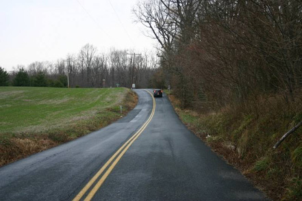
Centerline for No Passing on a horizontal curve.
The table below summarizes MUTCD requirements for centerline marking of two-way roads.
|
Area type |
Road Class |
Lanes |
ADT |
Travel Width (ft) |
|
|---|---|---|---|---|---|---|
REQUIRED |
Urban |
Collectors |
Arterials |
2 |
6000 + |
20+ |
All |
All |
|
3+ |
|
|
|
RECOMMENDED |
Urban |
Collectors |
Arterials |
2 |
4000+ |
20+ |
Rural |
Collectors |
Arterials |
2 |
3000+ |
18+ |
|
MAY CONSIDER |
Any |
Any |
2 |
Any |
16+ |
|
The MUTCD also states that "Engineering judgment should be used in determining whether to place centerline markings on travel ways less than 16 ft wide because of the potential for traffic encroaching on the pavement edges, traffic being affected by parked vehicles, and traffic encroaching into the opposing lane." Therefore, when an agency identifies a curved section as a potential safety problem, and the road segment does not have a centerline, this should be the first, minimal treatment applied. When the curve carries a low traffic volume (fewer than 200 vehicles per day) and/or the pavement is less than 16 ft wide, consider using post delineators, chevrons, or curve warning signs, even though the centerline is not deemed appropriate.
Road agencies commonly use a variety of paint-based materials and thermoplastic for the centerline markings. The specific material to be used depends on what an agency normally uses for its pavement marking applications. In general, thermoplastic markings are more cost-effective as they last much longer than paint materials. However, their higher initial costs may rule out their use on low-volume rural roads.
Other materials agencies can use for centerlines include a variety of raised pavement markers and "profile" thermoplastics. Chapter 3 discusses these supplemental devices. Also, chapter 5 discusses the use of rumble strips as a supplement to centerline pavement markings.
The standard width for each stripe of a centerline stripe is 4 in to 6 in, with the 4-in line more common. A wide line is simply twice the width of a standard line. There is no known safety benefit to having a wider centerline other than it provides a larger visual marking for motorists. When a double line is called for, such as when passing is not allowed, the normal practice in most jurisdictions is to separate the two lines by a measure approximately equal to the width of a single line—4 in to 6 in.
A 1996 Kentucky study estimated that including centerline markings reduced crashes by 35 percent. However, this study considered entire roadway sections, not individual curves. Other studies report much smaller benefits. These varying results suggest that agencies can expect safety benefits from installing centerline markings but that the magnitude of the benefits will vary based upon roadway and traffic characteristics.
The cost to apply pavement markings varies, depending on several factors. For example, the material used—paint or thermoplastic; does the agency’s own crew or an outside contractor perform the work; and is a single curve or several locations to be treated? Individual agencies are aware of their costs for applying pavement markings.
Edge line pavement markings define or delineate the edge of a roadway. It provides a visual reference to guide motorists and helps prevent them from drifting onto the shoulder and roadside area. For horizontal curves, regardless of the road type, edge line markings are a solid white line at the right edge of the travel lane (i.e., not including any shoulder). With the centerline, or adjacent lane line for a multilane road, it defines the travel lane for the road user. As with the centerline, edge lines can be applied just prior to and within the curved section, although it typically is applied to an entire section of roadway when used.
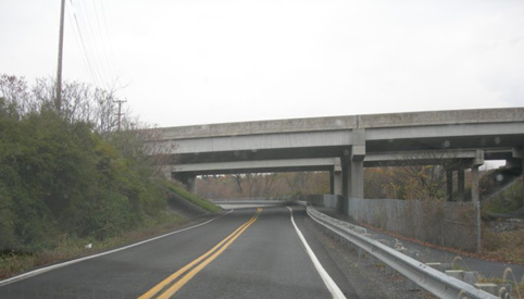
Centerline and edge line for two-lane road.
The MUTCD requires (standard) edge lines only for ". . . rural arterials with a traveled way of 20 ft or more in width and an average daily traffic (ADT) of 6,000 vehicles per day or greater." They are recommended (guidance) for ". . . rural arterials and collectors with a traveled way of 20 ft or more in width and an ADT of 3,000 vehicles per day" or any other paved road where an engineering study identifies a need for edge line markings.
It is not necessary to have a centerline on the road to add an edge line, but be cautious. On a narrow two-way road, white lines applied on both edges, without a yellow centerline marking, may signal to the motorist that the road is one-way.
The same materials discussed for the centerlines apply to edge lines. The exception is raised pavement markers (RPMs), which the MUTCD prohibits either as a substitute or supplement to the edge line. The rationale is that under wet night conditions when only the RPMs are visible, edge line RPMs can confuse drivers who could misinterpret them as marking the lane line. Also, RPMs on an edge line can cause bicyclists using the shoulder to lose control. Some States have used the profile marking design, which is discussed in the next chapter.
As with other longitudinal pavement markings, the standard edge line width is 4 in to 6 in, with the 4-in line used most. Six-inch edge lines are common on freeways and can be found on some lower class roads as well. Using a "wide" edge line (8 in to 12 in) on just the curved section, while not common, has been used to "emphasize" the curve section and provide a visually stronger guide for the motorist. However, do not use a wide edge line on roadways with a pavement width less than 20 ft, as it could cause motorists to move too far left into the opposing lane.
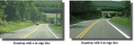
A wide (8-in) edge line provides a stronger visual guide.
A New York study found that standard edge lines on curvy two-lane roads reduced total crashes by 5 percent and fixed object crashes by 17 percent. Also, the Low Cost Local Road Safety Solutions report documents the safety benefit of adding an edge line and provides additional information on low-cost strategies for curves and other roadway locations. While these evaluations were conducted on sections of roads, agencies should assume that a safety benefit would be realized for individual curves. As for wider edge lines, the same report cites several studies citing a safety benefit from wider edge lines. The report also cites motorists’ preference, especially elderly drivers.
Cost
Comments regarding the cost of centerlines apply equally to edge line treatment.
The MUTCD prescribes several Horizontal Alignment signs to give drivers advance warning of a horizontal curve. For a single curve section, there are four signs:
For sections with a more than one curve in close proximity, there are three advance warning signs:
Not all horizontal curves require a Horizontal Alignment sign. Curves that have: (1) gentle to moderate curvature for which a speed advisory is not necessary, (2) adequate sight distance through the curve, and (3) adequate pavement markings and/or raised pavement markings and delineators, likely do not require even the Curve (W1-2) sign. As the MUTCD states, use the Curve sign where there is an advisory speed of greater than 30 mi/h and the Turn sign when the advisory speed is 30 mi/h or less. However, this is subject to engineering judgment that considers the traffic volume, type of road, and other factors. Use the Hairpin Curve sign when the curve is 135 degrees or more. The Loop sign is usually limited to 270-degree loops found on cloverleaf interchange ramps; it is not addressed in this publication.
The two sequential curves signs (left turning followed by right turning or vice versa) are:
The guidance is the same for selecting a Turn or Curve sign and agencies should base their decision on the advisory speed, as with the single Turn and Curve signs.
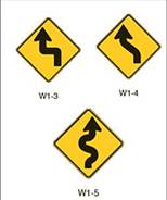
For road segments with three or more alignment changes in opposite directions in relatively close proximity, the Winding Road (W1-5) sign is appropriate.
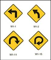
The MUTCD prescribes Horizontal Alignment Signs for advanced warning of a single curve section.
Advance warning signs for sections with more than one curve in close proximity.
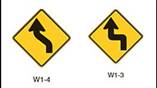
Two options for two sequential curves.

Winding Road sign for three or more alignment changes in close proximity.
Depending on the geometry of the curve or sets of curves, place the appropriate sign the distance in advance of the point of curvature, as shown in the table that follows. This table is based on Table 2C-4 of the MUTCD. For example, if the posted speed of the road is 50 mi/h and the curve has a posted advisory speed of 30 mi/h, then agencies would place the sign 100 ft before the point of curvature.
Posted or 85th-Percentile Speed (mi/h) |
Advance Placement Distance (Feet) for Advisory speed of the curve (mi/h) of |
||||||
|---|---|---|---|---|---|---|---|
10 |
20 |
30 |
40 |
50 |
60 |
70 |
|
20 |
n/a1 |
-- |
-- |
-- |
-- |
-- |
-- |
25 |
n/a1 |
n/a1 |
-- |
-- |
-- |
-- |
-- |
30 |
n/a1 |
n/a1 |
-- |
-- |
-- |
-- |
-- |
35 |
n/a1 |
n/a1 |
n/a1 |
-- |
-- |
-- |
-- |
40 |
n/a1 |
n/a1 |
n/a1 |
-- |
-- |
-- |
-- |
45 |
125 |
n/a1 |
n/a1 |
n/a1 |
-- |
-- |
-- |
50 |
200 |
150 |
100 |
n/a1 |
-- |
-- |
-- |
55 |
275 |
225 |
175 |
100 |
n/a1 |
-- |
-- |
60 |
350 |
300 |
250 |
175 |
n/a1 |
-- |
-- |
65 |
425 |
400 |
350 |
275 |
175 |
n/a1 |
-- |
70 |
525 |
500 |
425 |
350 |
250 |
150 |
-- |
75 |
625 |
600 |
525 |
450 |
350 |
250 |
100 |
1 No suggested distances are provided for these speeds, as the placement location depends on site conditions and other signing to provide an adequate advance warning for the driver.
This sign, and others discussed in this publication, should be placed in rural areas as illustrated.
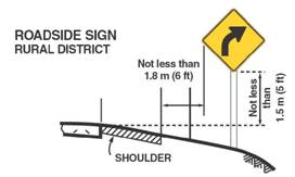
Offset and height placement for signs on rural roads.
Traffic signs of all types use retroreflective sheeting to ensure they are visible to drivers at night or in periods of low light. Over the last several years, agencies have transitioned from using engineering grade (Type I), to high-intensity grade (Type III), and even microprismatic sheeting (Type V). Each higher grade provides a brighter and longer lasting sign—but with increasing unit costs for each.
A 1968 evaluation of curve warning signs reported that installing warning signs can reduce crashes by 18 percent. No recent research identifies or evaluates this device, but a beneficial safety effect seems likely with their proper use.
An Advisory Speed plaque (W13-1) is simply a sign placed below a Horizontal Alignment sign (discussed above) to advise motorists of the safe speed through the curve(s). It is not the legal speed limit.
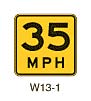
MUTCD Advisory Speed Plaque.
The MUTCD requires an engineering study to determine if an advisory speed is necessary for the condition. The MUTCD further states that ". . . the advisory speed may be the 85th-percentile speed of free-flowing traffic, the speed corresponding to a 16-degree ball bank indicator reading, or the speed otherwise determined by an engineering study because of unusual circumstances." The Traffic Control Devices Handbook provides further guidance on when to use an Advisory Speed Plaque. It also is suggests using the plaque whenever the difference between the advisory speed and the posted speed is 6 mi/h or greater.

The Traffic Control Devices Handbook provides additional guidance on devices found in the MUTCD.
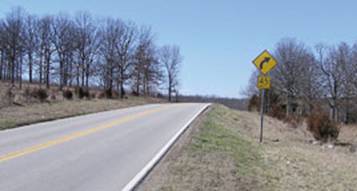
Photo source: Missouri DOT
Curve Horizontal Alignment sign with an Advisory Speed Plaque warns the driver of an approaching curve over the crest of a hill.
The One-Direction Large Arrow sign (W1-6) is used to define a change in horizontal alignment. Usually only one of these signs is used for a horizontal curve. It is typically placed on the outside of the curve directly in line with the approaching tangent section. Nothing in the MUTCD limits using multiple signs along the curve, but in this case, it would be more reasonable to use a series of Chevron (W1-8) signs. Install this Large Arrow sign only on the outside of a turn or curve in line with, and at approximately a right angle to approaching traffic.
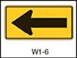
One-Direction Large Arrow Sign.
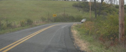
One direction Large Arrow Sign placed within curve.
MUTCD guidance regarding the application of this sign is to install either the One-Direction Large Arrow sign or the Chevron Alignment sign when the Hairpin Curve sign or the Loop sign is installed. Based on standard practice, this sign is limited to sharper curves (turns). It should not be used when there is no advisory speed plaque.
Agencies can combine the Turn (W1-1) sign or the Curve (W1-2) sign with the Advisory Speed (W13-1) plaque to form a combination Turn/Advisory Speed (W1-1a) sign or a combination Curve/Advisory Speed (W1-2a) sign. Use it as a supplement to (not a replacement for) the advance Horizontal Alignment sign and Advisory Speed plaque, and place it at the beginning of the turn or curve. The sign is intended to remind motorists of the need to slow down as they begin to negotiate the alignment change.
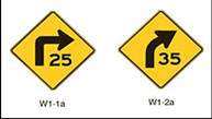
Combination Horizontal Alignment / Advisory Speed Signs.
The MUTCD contains no guidance as to when to use these signs, so it is up to an agency’s "engineering judgment." It is probably best not use it when the distance from the advance horizontal alignment sign and the point of curvature is 200 ft or less because the two signs would be too close together. Where this situation occurs, use the Curve Speed sign, which is discussed next.
The Curve Speed (W13-5) sign, serves a similar function as the Combination Horizontal Alignment/Advisory Speed sign. It is used to remind motorists of the advisory speed and, if appropriate, where the recommended (advisory) speed changes with the road curvature, such as for a compound or spiral curve design. Place the sign within the curve either on the inside or outside of the curve to increase its visibility. Although a special situation may call for both the Curve Speed sign and the Combination Horizontal Alignment/Advisory Speed sign, use one or the other, not both.
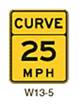
Curve Speed Sign.
While designated as a warning sign in the MUTCD, the Chevron Alignment (W1-8) sign is intended to emphasize and guide drivers through a change in horizontal alignment. Because of their pattern and size and that several of the signs are in view of the motorist, they define the direction and sharpness of the curve the best of all the traffic control devices. When the chevron sign is used, agencies will also need one of the advance curve warning signs previously discussed.
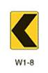
Chevron Alignment Sign
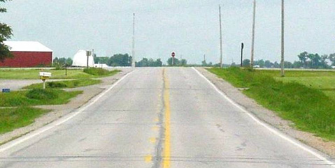
Before installation of Chevrons. After installation of Chevrons.
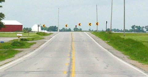
The installation of Chevrons provides guidance for the approaching curve.
Other than to state that the Chevron Alignment sign may be used as an alternative to supplement to standard delineators or to the One-Direction Large Arrow (W1-6) sign, the MUTCD provides no specific guidance as to when agencies should use the Chevron Alignment sign. The Traffic Control Devices Handbook suggests installing Chevrons when the difference between the advisory speed and posted speed is 25 mi/h or greater.
Install a series of these signs on the outside of turn or curve, positioned in line with approaching traffic at approximately a right angle to a driver’s line of sight. On two-lane, two-way roads, use two-sided Chevron signs properly aimed to guide traffic traveling both directions.
The MUTCD does not specify spacing of the signs; however, it does recommend that spacing allow the motorist to view at least two signs until the change in alignment eliminates the need for the signs. The following figure illustrates a layout of these devices on a curve. Position Chevron signs 5 ft above the surface in rural areas, and 7 ft in urban areas. Additionally, the following pages provide examples of spacing charts developed by two State DOTs.
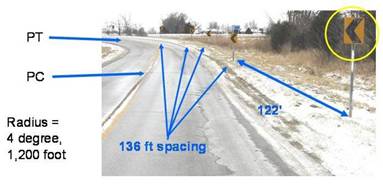
Layout of Chevrons.
| Advisory Speed Limit (mi/h) | Chevron Spacing (ft) |
|---|---|
| 15 | 40 |
| 20 | 80 |
| 25 | 80 |
| 30 | 80 |
| 35 | 120 |
| 40 | 120 |
| 45 | 160 |
| 50 | 160 |
| 55 | 160 |
| 60 | 200 |
| 65 | 200 |
NOTE: The above spacing distances apply to points within the curve. Approach and departure spacing distances are twice those shown above. |
|
Recommended Chevron Spacing |
||||
|---|---|---|---|---|
DEGREE OF CURVE |
RADIUS (feet) |
SPACING |
||
CURVE (feet) |
TURN (feet) |
TANGENT (feet) |
||
|
10000 |
400 |
200 |
200 |
1 |
|
304 |
152 |
200 |
|
5000 |
282 |
141 |
200 |
|
3000 |
218 |
109 |
196 |
2 |
|
212 |
106 |
191 |
|
2500 |
198 |
99 |
178 |
|
2000 |
176 |
88 |
158 |
3 |
|
172 |
86 |
155 |
|
1800 |
168 |
84 |
151 |
|
1600 |
156 |
78 |
140 |
4 |
|
148 |
74 |
133 |
|
1400 |
148 |
74 |
133 |
|
1200 |
136 |
68 |
122 |
5 |
|
132 |
66 |
119 |
|
1000 |
124 |
62 |
112 |
|
900 |
116 |
58 |
104 |
7 |
|
110 |
55 |
99 |
|
800 |
110 |
55 |
99 |
|
700 |
102 |
51 |
92 |
9 |
|
96 |
48 |
86 |
|
600 |
94 |
47 |
85 |
|
500 |
84 |
42 |
76 |
12 |
|
82 |
41 |
74 |
|
400 |
74 |
37 |
67 |
15 |
|
72 |
36 |
65 |
|
350 |
70 |
35 |
63 |
18 |
|
66 |
33 |
59 |
|
300 |
64 |
32 |
58 |
21 |
|
60 |
30 |
54 |
|
250 |
56 |
28 |
50 |
25 |
|
56 |
28 |
50 |
|
200 |
48 |
24 |
43 |
30 |
|
48 |
24 |
43 |
|
150 |
40 |
20 |
36 |
40 |
|
38 |
19 |
34 |
|
100 |
28 |
14 |
25 |
Effectiveness
Although the effectiveness of Chevron signs in reducing crashes has not been established, the signs have been shown to reduce vehicle encroachments onto the centerline in curves where the degree of curvature is more than 7 degrees.
Cost
The cost to apply Chevrons around a curve will vary with the number of signs installed. A typical installation of about 10 signs would cost approximately $500.
A commonly used device for showing the curve alignment to the motorist is the delineator—a retroreflective device mounted above the roadway surface and along the side of the roadway in a series to show roadway alignment. A delineator is considered a guidance device rather than a warning device and is most effective at night and during adverse weather when pavement markings are not visible.
The delineator device is typically either circular or rectangular with a 3-in minimum dimension. They are usually mounted on posts (which can have retroreflective material as well) 4 ft above the pavement. They can be placed on barriers if they are present—if there are none, then delineators are placed on lightweight breakaway posts. As shown in the photo, the delineators are rectangular reflectors placed on a flexible post. The application shown is on a ramp, but they are also used for curved sections of roadways.
The MUTCD requires the color of the delineators to match the color of theadjacent edge line. For example on a curve on a two-way road, the edge lines on both sides of the road are white, so if delineators are used on the left side of the road they must be white. Delineators on the right side are also white.
Application Guideline
The MUTCD does not provide any guidance as to when to install this device. However, given their relatively low cost, they should be considered for curves where any of the advance curve warning signs are used. For curves greater than 7-degree, the Chevron sign, discussed next, might be more cost-effective.
Design
Delineators are placed on the right shoulder and, therefore, the reflectors are white (clear) to match the white edge line. Adjust spacing of delineators on approaches to and throughout the horizontal curves so that several delineators are always visible to the motorist. Follow the approximate spacing shown in the table on the next page.
Effectiveness
The Low Cost Local Road Safety Solutions publication cites a 1966 Ohio Department of Transportation Study which found that post-mounted delineators on rural two-lane curves reduced run-off-road crashes by 15 percent.
Cost
The cost of post delineators applied to a single curve will vary depending upon the number used and the material for the post and retroreflector.
Further Information
For further information on post delineators, see Roadway Delineation Practices Handbook (https://www.fhwa.dot.gov/tfhrc/safety/pubs/93001/intro.htm).
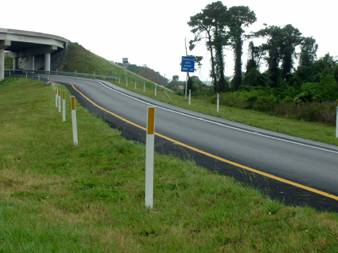
Post delineators installed on a ramp.
Approximate Spacing for Delineators on Horizontal Curves.
Radius Of Curve (ft) |
Approximate Spacing On Curve (ft) |
|---|---|
50 |
20 |
115 |
25 |
180 |
35 |
250 |
40 |
300 |
50 |
400 |
55 |
500 |
65 |
600 |
70 |
700 |
75 |
800 |
80 |
900 |
85 |
1000 |
90 |
2 See Traffic Control Devices Handbook for use of a ball bank indicator.
| < Previous | Table of Contents | Next > |

