U.S. Department of Transportation
Federal Highway Administration
1200 New Jersey Avenue, SE
Washington, DC 20590
202-366-4000
| < Previous | Table of Contents | Next > |
Most basic devices described in chapter 2 can be improved in different ways so that they can be seen farther away. The sooner a motorist is able to see a device and recognize its meaning, the more time there is to respond. This chapter discusses the following seven treatments have proved effective in getting motorists’ attention:
The table below shows the sizes of the signs described in the previous chapter for conventional roads. The MUTCD prescribes the use of the "conventional road" sizes for typical situations. The minimum size is not recommended. However, the MUTCD allows their use on low-speed roadways where the reduced letter size remains adequate for the warning or where physical conditions prevent using a larger size. The MUTCD also states that ". . . oversized and larger signs may be used for those special applications where speed, volume, or other factors result in conditions where increased emphasis, improved recognition, or increased legibility would be desirable." A horizontal curve identified as a safety problem would likely meet this application guideline. Thus, consider larger sizes, typically in 6-in increments for both dimensions.
Warning Sign Sizes (in).
Description Shape |
Description Sign Series |
Minimum |
Conventional Road |
Expressway |
Freeway |
|---|---|---|---|---|---|
Diamond |
W1-1, W1-2, W1-3, W1-4, W1-5, W1-11, W1-15, W1-1a, W1-2a |
24 x 24 |
30 x 30 |
36 x 36 |
48 x 48 |
Rectangular |
W1-6 |
36 x 18 |
48 x 24 |
-- |
-- |
W1-8 |
12 x 18 |
18 x 24 |
30 x 36 |
36 x 48 |
|
W13-5 |
24 x 30 |
24 x 30 |
36 x 48 |
48 x 60 |
Source: MUTCD, Table 2C-2.
"Doubling-up" simply refers to situations where agencies install a second, identical sign on the left side of the roadway. Agencies can do this for the basic signs discussed in the previous chapter. Doubling-up increases the opportunity for the motorist to see the sign, and more importantly, respond to the message. Doubling-up is a candidate treatment when visibility of the single right-hand side sign is less than desirable.
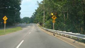
Doubling-up of the sign proved effective at this site because tree limbs partially blocked the right side sign.
Another way to make signs more visible or more noticeable to motorists is to use high-intensity retroreflective sheeting and fluorescent-yellow sheeting. As noted in chapter 2, the retroreflective sheeting for signs is available in different intensity grades. Signs made with high-intensity sheeting can help motorists see them from a longer distance at nighttime visibility. For more information on types of retroreflective sheeting, visit: http://safety.fhwa.dot.gov/roadway_dept/night_visib/
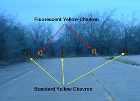
Fluorescent yellow increases visibility of warning signs and certain other signs, such as the Chevron sign. Again, the higher intensity sheeting makes the sign more visible to motorists who can recognize and respond to it earlier. This visual advantage works day and night.
Initial research based on eye-tracking data indicates that upgrading conventional yellow chevrons to fluorescent yellow, while not affecting speed or lane placement, improves driver perception of the signs. This improved driver performance effect suggests a potential safety effect.
The estimated cost of an 18-in by 24-in Chevron sign with Type III sheeting is about $335. This estimate was based on a unit price of $1.20/ft2 for sheeting. Applying an estimated cost of $4.00/ft2 of fluorescent color microprismatic sheeting brings the total sign cost to $343, a cost increase of only 2.4 percent.
Source: Texas Transportation Institute
Stimulus photo illustrating enhanced chevron visibility.
Using flashing beacons with a warning sign is another way to gain motorists’ attention. The beacons are typically used with one of the advance Horizontal Alignment signs for a horizontal curve. There are no published guidelines for when they are appropriate, but reasonable guidelines are to limit them to locations where other treatments have not solved a safety problem. One factor limiting their use is the availability of an accessible power source, although agencies can use reliable solar power panel systems as well.
The beacons used for this treatment are the circular yellow sections from a standard traffic signal. Agencies can install this with one or more beacons, but the photo on the right shows a typical arrangement. The beacons can be flashed either alternately or simultaneously. To prevent the flashing light from masking the sign message, locate the beacon signal housing at least 12 in outside of the nearest edge of the sign.
The safety effectiveness of this particular treatment is yet to be established, but a 1970s study evaluated the effects of signing to warn drivers of wet weather skidding hazards at horizontal curves. The study concluded that agencies could significantly reduce vehicle speed by adding flashing beacons on the curve warning sign.
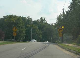
Typical arrangement of signs and flashing beacons.
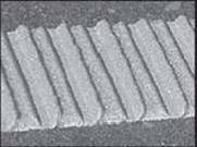
Agencies apply thermoplastic markings to create a profile marking, which also produces a rumble effect and enhances visibility of the marking. A few agencies have used this treatment with good results, but there is no firm evaluation. As snow plowing can destroy this marking, its use is sometimes limited to warmer climate locations.
The California Department of Transportation (Caltrans) has used two types—raised and inverted profile patterns, as pictured on the next page and in the accompanying design specification.
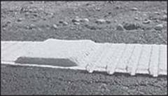
(Source: Caltrans)
Raised profile thermoplastic marker.
(Source: Caltrans)
Inverted profile thermoplastic marker.
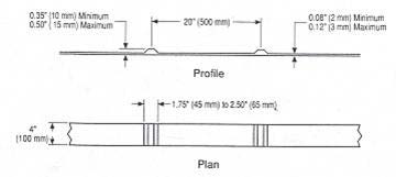
A raised profile where a thicker layer of thermoplastic is applied on 20-in centers along the stripe.
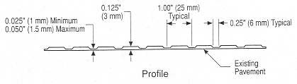
An inverted profile where depressions are made every 1 in along the stripe.
In many situations, agencies will install raised pavement markers (RPMs) to supplement or substitute for pavement markings. There are a variety of types and they can be reflective or nonreflective. For geographic areas where snow is common, the reflective device is encased in an iron casting or recessed below the pavement surface in a grooved section to prevent damage by snow plows. Agencies typically apply the markers within a long roadway section; the advantage is that they provide a longer visual range of delineation for motorists, especially at night (if reflective) and during wet conditions. RPMs also work well when applied to a single curve or curvy section of roadway. The RPMs also provide an auditory warning to the motorist who travels on them.
For more information about using raised pavement markers, visit the MUTCD (http://mutcd.fhwa.dot.gov/HTM/2003r1/part3/part3a.htm) and in the Roadway Delineation Practices Handbook (https://www.fhwa.dot.gov/tfhrc/safety/pubs/93001/intro.htm).
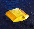
Standard Raised Pavement Marker (yellow for centerline).
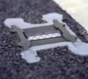
Snowplowable Raised Pavement Marker.
While studies of the operational effects have shown RPMs can reduce the variation in lane placement and move vehicles away from the centerline, studies of crash changes have produced mixed results. They show a safety benefit on roadways with gentle curvature (less than 3.5 degrees) and relatively high volumes (greater than 5,000 veh/day), and safety disbenefits for roadways with sharper curvature (greater than 3.5 degrees) under all volume conditions. It has been hypothesized that the disbenefit results from the higher speeds because motorists feel safer with the RPMs providing alignment information even under wet nighttime conditions.
A comprehensive guide on all types of delineation devices.
| < Previous | Table of Contents | Next > |

