U.S. Department of Transportation
Federal Highway Administration
1200 New Jersey Avenue, SE
Washington, DC 20590
202-366-4000
A median island narrowing is a raised island located along the street centerline that narrows the travel lanes at that location (see Figure 3.18.1). The visual appearance of narrowed lanes encourages a motorist to slow.
A median island is physically different from and serves a different purpose as a standard median on a 4-or-more-lane roadway. The latter median provides separation between opposing vehicle travel lanes, an opportunity for landscaping or visual enhancements to a roadway corridor, and a place of refuge for a pedestrian crossing a multi-lane street – all in support of improved and safe traffic flow.
A median island may simply be a painted area that is designated for non-automobile use. But a median island is most effective when it is defined by a raised curb and landscaped to further reduce the open feel of a street (see Figure 3.18.2). Median islands often incorporate textured pavement on the island itself, particularly for a median island without a raised concrete curb.
A median island can often double as a pedestrian refuge island if a cut in the island is provided along a marked crosswalk. Where there is an existing midblock crosswalk, it is desirable to locate the median island at the crosswalk.
When placed at or near the entrance to a neighborhood, a median island provides a visual cue to the motorist about the preferred vehicle speed (see Figure 3.18.3). If a median island has textured pavement on either side or a monument sign, it can serve as a gateway or entry feature.
[A median island is also called a center island narrowing, midblock median, median slow point, median choker, and refuge island (when part of a marked crosswalk)]
[A median island that narrows lanes from the centerline is the opposite of a choker that narrows lanes toward the centerline]
[Eight field studies of 15 median islands measured reductions between 1 and 8 mph for 85th percentile speeds (Source: FHWA, Engineering Speed Management Countermeasures: A Desktop Reference of Potential Effectiveness in Reducing Speed, July 2014) http://www.safety.fhwa.dot.gov/speedmgt/ref_mats/eng_count/2014/reducing_speed.cfm]

Figure 3.18.1. Median Island Schematic
(Source: Delaware Department of Transportation)

Figure 3.18.2. Landscaped Median Island
(Source: Ian Lockwood)

Figure 3.18.3. Landscaped Oval Median Island
(Source: Ken Sides)
| Appropriate Application – Median Island | |
| Type of Street | Appropriate for an arterial, collector, or local street – whether in an urban or suburban setting |
| Intersection or Roadway Segment | Can be placed at a midblock location or on the approach to an intersection If placed through an intersection, a median island is considered a median barrier [provide link to section 3.24] When placed on a curve, can be effective in reducing or retaining low vehicle speeds (see Figure 3.18.4) May be effective when placed immediately downstream of an intersection; island forces motorist to turn in accordance with curb radius (i.e., and not swing wide at a higher speed) |
| Roadway Cross-Section | Appropriate only on a two-way street; number of lanes in each direction can be one or more Typically installed only on a roadway with an urban cross-section (i.e., curb and gutter) Can be applied on a cross-section both with and without sidewalks or bicycle facilities Can be applied on a roadway with on-street parking as long as there is sufficient lane width for the design vehicle If intended to serve as a pedestrian refuge for a pedestrian crossing (along with an at-grade or raised crosswalk), median width of at least 6 feet is needed (see Figure 3.18.5) Can be used in combination with a curb extension on one or both sides of the street |
| Speed Limit | Can be appropriate for any common urban speed limit, provided an adequate shy distance is provided between the travel lane and the median island curb; Portland OR uses a maximum of 45 mph; Pennsylvania uses 40 mph; Delaware uses 35 mph; and South Carolina uses 30 mph |
| Vehicle Traffic Volume | Can be appropriate at all levels of traffic volume |
| Emergency Route | Can be appropriate along a primary emergency vehicle route or street that provides access to a hospital or emergency medical services if adequate turning radii can be provided |
| Transit Route | Can be appropriate along a bus transit route if appropriate turning radii can be provided |
| Access Route | Typically not appropriate along a primary access route to an industrial site; a roadway cross-section designed to accommodate large combination vehicles at a median island will likely result in a travel lane that is too wide to have an effect on passenger vehicle speeds |
| Grade | Can be installed on a crest vertical curve only if there is adequate stopping sight distance or if appropriate warning signs are provided Maximum grade should comply with local standards and criteria; Delaware uses a maximum grade of 6 percent |

Figure 3.18.4. Median Island Near Curve at Entrance to Residential Area
(Source: Scott Wainwright)

Figure 3.18.5. Median Island with Crosswalk
(Source: Dona Sauerburger)
| Effects and Issues – Median Island | |
| Vehicle Speed | Traffic speeds likely to decrease slightly (typically between 1 and 5 mph, with reductions of 2 to 3 mph being the most common); Figures 3.18.6 and 3.18.7 provide photos of median islands placed at intersections; Figures 3.18.8 and 3.18.9 provide photos of median islands placed midblock |
| Vehicle Volume | Has little effect on traffic volumes |
| Pedestrian Safety and Mobility | Safety of a pedestrian crossing collector or arterial street can be significantly improved without substantial delay to vehicular traffic Shortens street crossing distance for pedestrian and serves as pedestrian refuge during two-stage crossing FHWA16 reports 46 percent reduction in pedestrian crashes at marked crosswalk and 39 percent reduction at unmarked crosswalk If wide enough to satisfy ADA ramp slope requirements, pedestrian can be elevated, potentially improving both line-of-sight and visibility to oncoming motorist Refer to Module 6 for additional discussion |
| Bicyclist Safety and Mobility | Reduces travelway width and forces bicyclist and motor vehicle to share travel lane; shared lane markings (sometimes known as a sharrow) and "bike may use full lane" signage could be appropriate |
| Motorist Safety and Mobility | Likely to have minimal effect on motorist mobility and safety Minimal impact on motorist comfort Separates opposing vehicle travel lanes and reduces opportunities for vehicle-vehicle collisions Can be used on horizontal curve to encourage slower operating speed and prevent vehicle from swinging wide across centerline |
| Emergency Vehicle Safety and Mobility | Retains sufficient width to allow for continued easy flow of emergency vehicles; may obstruct emergency vehicle from making turn directly at destination driveway (solution is to travel in the wrong direction for a short distance next to the median island) Refer to Module 5 for additional discussion |
| Large Vehicle Safety and Mobility | Retains sufficient width to allow for the continued easy flow of large vehicles like combination trucks; may obstruct large vehicle from making turn directly at destination driveway (solution is to travel the wrong way for a short distance next to the median island) Refer to Module 5 for additional discussion |
| Accessibility of Adjacent Property | May require removal of some on-street parking and may, therefore, slightly reduce the accessibility of adjacent property Can restrict direct access to a driveway that is located within limits of median island |
| Environment | Can be used as a landscaping opportunity, provided visibility of pedestrian in crossing is not compromised |
| Design Issues | May require relocation of drainage features such as catch basins, concrete channels, valley gutters, inlets, and trench drains May require relocation of above- and below-ground utilities |
16 Source: FHWA, Proven Safety Countermeasures

Figure 3.18.6. Median Island at Intersection
(Source: Scott Batson)

Figure 3.18.7. Small Median Islands at Intersection
(Source: Scott Batson)

Figure 3.18.8. Short Midblock Median Island
(Source: Lewis Grimm)

Figure 3.18.9. Long Midblock Median Island
(Source: James R. Barrera)
A median island can be designed in conjunction with an at-grade crosswalk or a vertical traffic calming feature (e.g., speed hump, speed table, raised crosswalk) to increase the likelihood of lower vehicle speeds.
If a median island is at least 6 feet wide, a pedestrian refuge area can be included in the design (see Figures 3.18.10 and 3.18.11). The island reduces the pedestrian/vehicle conflict area and allows a pedestrian to cross one direction of traffic at a time. The pedestrian crossing can be level with the pavement (with a corresponding break in the median island), or raised, such that the pedestrian crossing is level with the sidewalk.
On-street parking should not be permitted along the curbing of a median island that is used for traffic calming. If the parking spaces are unoccupied, the potential roadway width reduction caused by the island (and its traffic calming effect) is absent.
A median island should not be placed in front of or in close proximity to a driveway, unless access control is desired.
A median island should include MUTCD compliant signs in order to alert motorists of the presence of the median island. Signs can be supplemented by landscaping.
A sample design for a median island is presented in Figure 3.18.12.

Figure 3.18.10. Median Island with Pedestrian Refuge and Offset Crosswalk
(Source: Scott Batson)

Figure 3.18.11. Median Island with Pedestrian Refuge
(Source: James R. Barrera)

Figure 3.18.12. Sample Design for Median Island
(Source: Delaware Department of Transportation)
W11-2
On-street parking can effectively narrow the roadway travel lanes by adding side friction to the traffic flow (see Figure 3.19.1). On-street parking can be allowed on one or both sides of a roadway. Or parking zones can be strategically located on alternate sides of a roadway to create a chicane effect.
Whether on-street parking can be an appropriate traffic calming measure is a direct function of its actual or potential usage (i.e., parking demand). In order for the presence of on-street parking to be an effective and safe traffic calming measure, it must be occupied with parked vehicles during the time when traffic calming is desired.
The different types of on-street parking (parallel and both front-in and back-in angled) have different horizontal width effects and operational effects.
Both parallel and angle vehicle parking can be protected through the use of protected parking bays or the use of a complementary traffic calming measure such as a corner extension, midblock choker, or chicane.

Figure 3.19.1. On-Street Parking Near Residences and Park
(Source: Robert Kahn)
Traffic Calming ePrimer
| Appropriate Application – On-Street Parking | |
| Type of Street | Appropriate for arterial, collector, and local streets in an urban or suburban setting (see Figure 3.19.2) |
| Intersection or Roadway Segment | Appropriate as a midblock measure and near an intersection |
| Roadway Cross-Section | Can be used on a one-way or two-way street Preferable to have an urban cross-section (i.e., curb and gutter) Can be applied both with and without a bicycle facility; the combination of parking and bicycle facilities may require extra width to protect bicyclists from car doors |
| Speed Limit | Can be appropriate for any common urban speed limit, provided an adequate shy distance is provided between the travel lane and the parking lane |
| Vehicle Traffic Volume | Can be appropriate at all levels of traffic volume |
| Emergency Route | Can be appropriate along a primary emergency vehicle route or street that provides access to a hospital or emergency medical services |
| Transit Route | Can be appropriate along a bus transit route |
| Access Route | Can be appropriate along a primary access route to a commercial or industrial site |
| Grade | Can be installed on a crest vertical curve only if there is adequate stopping sight distance or if appropriate warning signs are provided Maximum grade should comply with local standards and criteria |

Figure 3.19.2. On-Street Parking in a Commercial Business District
(Source: Omni-Means, Ltd.)
| Effects and Issues – On-Street Parking | |
| Vehicle Speed | Can slow traffic by reducing effective travel lane width; typical reduction in speed ranges between 1 and 5 mph, with reduction of 2 to 3 mph being the most common Most pronounced effect on speed occurs on a narrow two-way street with parking on both sides (see Figure 3.19.3) If half or more of the block face is not occupied by parked vehicles, the effect on vehicle speeds lessens and is negligible; the use of corner extensions or chokers could counter the effect of "open" parking spaces |
| Vehicle Volume | Little effect on traffic volumes |
| Pedestrian Safety and Mobility | Little effect on number and severity of pedestrian/vehicle conflicts, except for the movement of persons to and from a parked vehicle Parked vehicles can serve as a buffer between moving vehicles and pedestrians on the sidewalk; this buffer provides a comfort level that is welcome for pedestrians, especially in an active commercial district Pedestrians moving between and around parked vehicles may be difficult to see for a motorist |
| Bicyclist Safety and Mobility | Can provide a designated bicycle lane or shared lane markings (sometimes known as a sharrow) with appropriate signage; presence of a designated bicycle lane between parked vehicles and travel lanes reduces the traffic calming effects of on-street parking The combination of parking and bicycle facilities may require extra width to protect bicyclists from car doors |
| Motorist Safety and Mobility | Likely to have minimal effect on motorist mobility and safety Minimal impact on motorist comfort |
| Emergency Vehicle Safety and Mobility | Retains sufficient width to allow for continued flow of emergency vehicles |
| Large Vehicle Safety and Mobility | Retains sufficient width to allow for continued flow of large vehicles like combination trucks Refer to Module 5 for additional discussion |
| Accessibility of Adjacent Property | Improves accessibility of adjacent property |
| Environment | Can be developed in combination with landscaping enhancements on corner extensions and chokers |
| Design Issues | Parallel parking is generally the preferred configuration to achieve vehicle speed reduction Angle parking is likely to be safer in a setting where pre-implementation traffic speeds are already low |

Figure 3.19.3. On-Street Parking on a Collector Street
(Source: Marshall Elizer)
On-street parking can be protected by a curb extension.
For a bicycle lane placed between the parking lane and the travel lane, the preferred bicycle lane width is 6 feet, with a minimum of 5 feet (see Figure 3.19.4). A width of up to 7 feet may be desirable if adjacent to a narrow parking lane with high parking turnover.

Figure 3.19.4. On-Street Parking with Adjacent Bicycle Lane
(Source: www.pedbikeimages.org / Dan Burden)
A road diet is the conversion of an undivided roadway to a cross-section with fewer or narrower through motor vehicle travel lanes. The most common application is the conversion of an undivided four-lane roadway to a three-lane roadway consisting of two through lanes and a center two-way left-turn lane (see Figure 3.20.1). The reduction in the number of lanes permits the inclusion of facilities for other uses, such as bicycle lanes, sidewalks, pedestrian refuge islands, transit uses, and on-street parking.
The FHWA Road Diet Informational Guide provides guidance on potential road diet applications and designs and their anticipated effects on safety and mobility http://www.safety.fhwa.dot.gov/road_diets/info_guide/.
[Seven field studies of 23 road diets measured crash reductions between 17 and 62 percent; another study of 15 sites found an overall crash reduction of 25 percent (Source: FHWA, Engineering Speed Management Countermeasures: A Desktop Reference of Potential Effectiveness in Reducing Crashes, July 2014) http://www.safety.fhwa.dot.gov/speedmgt/ref_mats/eng_count/2014/reducing_crashes.cfm]
[Two field studies of two road diets measured reductions between 1 and 2 mph for 85th percentile speeds (Source: FHWA, Engineering Speed Management Countermeasures: A Desktop Reference of Potential Effectiveness in Reducing Speed, July 2014 http://www.safety.fhwa.dot.gov/speedmgt/ref_mats/eng_count/2014/reducing_speed.cfm]
A video that explains and demonstrates road diets can be accessed at the following hyperlink:
https://vimeo.com/21903160 (Source: Streetfilms)
A video that shows the product of a road diet and complete streets project can be accessed at the following hyperlink: https://www.youtube.com/watch?v=pi50nMDppYA (Source: Carlisle, Pennsylvania)

Figure 3.20.1. Road Diet Schematic
(Source: FHWA Road Diet Information Guide)
| Appropriate Application – Road Diet | |
| Type of Street | Appropriate for arterial, collector, and local streets in an urban, suburban, or rural setting |
| Intersection or Roadway Segment | Applied along a roadway segment (or along a series of segments that encompass intersections) as shown in Figures 3.20.2 and 3.20.3 |
| Roadway Cross-Section | Most common on a four-lane section; can be applied on a wide two-lane section |
| Speed Limit | Can be appropriate for any common urban speed limit |
| Vehicle Traffic Volume | Can be appropriate for any volume that can be accommodated by revised cross-section; commonly-referenced threshold is a peak hour volume of 1,000 vehicles per post-implementation through travel lane; a lower volume indicates a road diet is likely feasible; higher volume requires further investigation Daily maximum values of 15,000, 18,000, and 25,000 established in Pasadena, CA, Lansing, MI, and Seattle, WA, respectively |
| Emergency Route | Can be appropriate along a primary emergency vehicle route or street that provides access to a hospital or emergency medical services |
| Transit Route | Can be appropriate along a bus transit route |
| Access Route | Can be appropriate along a primary access route to a commercial or industrial site |
| Grade | Can be installed on a crest vertical curve only if there is adequate stopping sight distance or if appropriate warning signs are provided Maximum grade should comply with local standards and criteria |

Figure 3.20.2. Example Cross-Section Prior to Road Diet
(Source: Scott Wainwright)

Figure 3.20.3. Example Cross-Section with Road Diet
(Source: Scott Wainwright)
| Effects and Issues – Road Diet | |
| Vehicle Speed | Elimination of a travel lane can reduce higher speeds that are achieved through passing |
| Vehicle Volume | Little effect on traffic volumes |
| Pedestrian Safety and Mobility | Reduces severity of pedestrian/vehicle conflicts through vehicle speed reduction Improves pedestrian ability to cross street safely by reducing the number of moving lanes of traffic to be viewed and crossed Provides space for potential median island that can serve as a refuge island and further improve pedestrian safety If road diet adds sidewalks to cross-section, pedestrian safety and mobility are improved |
| Bicyclist Safety and Mobility | Reduces severity of bicyclist/vehicle conflicts through vehicle speed reduction If road diet adds bicycle lanes to cross-section, bicyclist safety and mobility are improved (see Figure 3.20.4) |
| Motorist Safety and Mobility | Expected crash reduction of between 19 and 47 percent Safety benefits from reduced vehicle speeds and from movement of left turning vehicles out of a through travel lane |
| Emergency Vehicle Safety and Mobility | Retains sufficient width to allow for continued flow of emergency vehicles |
| Large Vehicle Safety and Mobility | Retains sufficient width to allow for continued flow of large vehicles like combination trucks |
| Accessibility of Adjacent Property | Provision of dedicated turning lane can improve accessibility of property along segment |
| Environment | Reallocation of cross-section elements could provide space for landscaping enhancements, but not typical |
| Design Issues | Cross-section transitions and appropriate treatment of road diet through intersections are key to safety benefits |

Figure 3.20.4. Road Diet with Buffered Bicycle Lanes
(Source: Hillary Orr)
Potential references:
A diagonal diverter is a physical barrier placed diagonally across a four-legged intersection. The barrier creates two unconnected intersections. Traffic approaching the intersection is restricted to one receiving leg, rather than three (see Figure 3.21.1).
A strategically placed diagonal diverter can reduce traffic volume by preventing straight-through traffic movements at an intersection.
[A diagonal diverter is also called a full diverter and a diagonal road closure.]
A cutout, gap, or channel can be provided in the diagonal diverter to allow at-grade bicyclist movement between all four legs of the intersection.
Pedestrians can and should be accommodated by pass-throughs or walkways across or through the diverter.
In order to enable emergency vehicle access through the diagonal diverter, breakaway or lockable bollards or gates have been used on a diverter.
[A field study of seven diagonal diverters measured an average reduction of 1 mph for 85th percentile speeds (Source: FHWA, Engineering Speed Management Countermeasures: A Desktop Reference of Potential Effectiveness in Reducing Speed, July 2014) http://www.safety.fhwa.dot.gov/speedmgt/ref_mats/eng_count/2014/reducing_speed.cfm]
It is important to consider where the diverted traffic is likely to shift, in particular the availability, capacity, and appropriateness of the alternative routes. As stated in Module 7, traffic shifts can create new issues that need to be addressed.
A single diagonal diverter may simply shift traffic onto other local streets. In order to shift through traffic to collector and arterial streets that can more effectively handle the traffic demand, a diagonal diverter can be installed in a group or cluster of diagonal diverters or other traffic calming measures that reduce cut-through volumes.
A video demonstrating a diagonal diverter can be accessed at the following hyperlink:
http://www.streetfilms.org/portland-or-traffic-calming-diagonal-diverter/
(Source: Streetfilms)

Figure 3.21.1. Diagonal Diverter Schematic
(Source: Delaware Department of Transportation)
| Appropriate Application – Diagonal Diverter | |
| Type of Street | Appropriate for subdivision, local, and minor collector streets Appropriate in both an urban and suburban setting |
| Intersection or Roadway Segment | Applicable only at an intersection |
| Roadway Cross-Section | Can be used on both one-way and two-way streets Typically found only on a roadway with an urban cross-section (i.e., curb and gutter) Can be applied both with and without a bicycle facility Can be applied on a roadway with on-street parking |
| Speed Limit | Requires slow vehicle speeds to negotiate the intersection sharp curve; typical maximum speed limit is 25 mph (see Figure 3.21.2) |
| Vehicle Traffic Volume | Can be appropriate if the traffic volume is relatively low; Pennsylvania uses a maximum of 3,500 daily vehicles |
| Emergency Route | Not appropriate along a primary emergency vehicle route or street that provides access to a hospital or emergency medical services |
| Transit Route | Not appropriate along a bus transit route that passes straight through the intersection unless transit route can be altered |
| Access Route | Not appropriate along a primary access route to a commercial or industrial site |
| Grade | Can be installed on a crest vertical curve only if there is adequate stopping sight distance or if appropriate warning signs are provided Maximum grade should comply with local standards and criteria; Delaware uses a maximum grade of 6 percent |

Figure 3.21.2. Diagonal Diverter in a Residential Area
(Source: Jeff Gulden)
| Effects and Issues – Diagonal Diverter | |
| Vehicle Speed | Forces motorist to slow to negotiate the diversion curve; vehicle speeds through intersection are function of severity of diversion curve (typically, 90 degrees) and the volume and distribution of traffic that passes through the corner Slight speed reduction could also be expected as far as 200 to 300 feet away from the intersection |
| Vehicle Volume | Forces all traffic that otherwise could pass straight through the intersection to divert to another path; portion may remain and pass through the diagonal diverter curve as part of its rerouted path; some will divert from intersection completely; Delaware reports typical 35 to 40 percent reductions in daily traffic volume; Pennsylvania reports reduction falls between 20 and 70 percent with most common being 35 percent Because of potential for significant impact on traffic patterns, can be controversial |
| Pedestrian Safety and Mobility | Improves with reduction in vehicle volume and slower vehicle speeds through intersection Pedestrian access through the diagonal diverter can be accommodated by providing a gap in the feature with curb ramps |
| Bicyclist Safety and Mobility | Improves with reduction in vehicle volume and slower vehicle speeds through intersection Bicyclist access through the diagonal diverter can be accommodated by providing a gap in the feature; opening can be level with or ramped to the pavement; appropriate bicycle-specific signing and striping can be installed to direct bicycle flow (see Figure 3.21.3) Refer to Module 6 for additional discussion |
| Motorist Safety and Mobility | Removes some of the conflicting traffic movements at an intersection |
| Emergency Vehicle Safety and Mobility | Typically, restricts emergency vehicles from passing straight through intersection; emergency access and response time are affected Can be modified to include removable delineators, breakaway or lockable bollards, lockable gates, low landscaping, or a mountable curb apron along with a passable area wide enough for an emergency vehicle; still adds delay for emergency services Refer to Module 5 for additional discussion |
| Large Vehicle Safety and Mobility | Restricts large vehicles from passing straight through the intersection; requires use of alternate path Refer to Module 5 for additional discussion |
| Accessibility of Adjacent Property | Blockage of vehicular traffic through intersection affects both through traffic and local traffic attempting to access the local street system; diverter reduces overall network connectivity, particularly for vehicle traffic, and causes the need for more circuitous routing to and from a property; overall property accessibility is affected |
| Environment | Can be used as landscaping opportunity |

Figure 3.21.3. Diagonal Diverter with Bicyclist
(Source: Creative Commons / Paul Krueger
The design for a diagonal diverter should maintain full lane widths. The intent of a narrowed cross-section is typically to reduce vehicle speed; for a diagonal diverter, it is not necessary to further reduce the speed of a turning motorist.
A diagonal diverter is designed for accessibility, not mobility. The radius should be the minimum needed to allow the design vehicle through, not related to the posted speed, per se.
A diagonal diverter should have a barrier-type curb in order to discourage unauthorized vehicles from traversing it.
Appropriate signs and markings need to be in place to help the motorist be aware of and see the diagonal diverter. Painted curbs, delineation, street lights, and advance warning directional arrow signs (e.g., Single Curve signs) should be considered. Parking Prohibited signs may also be required along the diverter.
A diagonal diverter can be landscaped for aesthetic reasons and also to reinforce the idea that the barrier is not to be traversed.
If the design needs to enable an emergency vehicle to pass through the diverter, a clear width of at least 12 feet should be left free of landscaping (14 feet is preferred). The traversable area should be clearly signed for emergency vehicle use only.
A diagonal diverter could provide an opening for a bicyclist to pass through the barrier. If a bicycle channel is provided, it should have bollards or planters or some vertical feature immediately adjacent to each edge of the channel in order to prevent use by general traffic.
Typical requirements for a diverter are illustrated in Figure 3.21.4. If a sidewalk is placed along the diverter, greater width will be needed on the diverter than is illustrated in the figure.
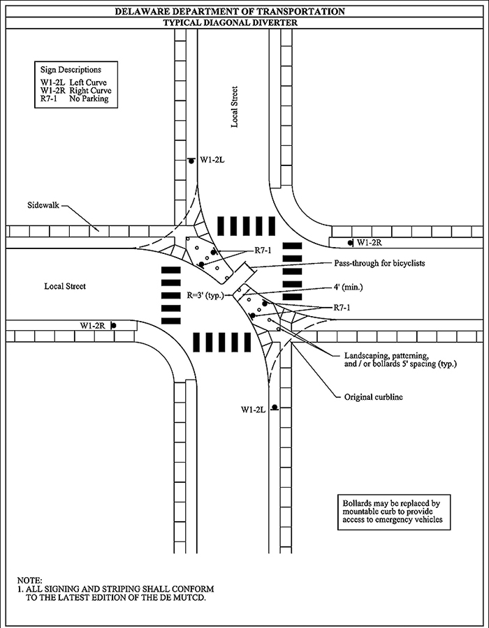
Figure 3.21.4. Sample Design for Diagonal Diverter
(Source: Delaware Department of Transportation)
A full street closure is a physical barrier placed across a street to close the street completely to through vehicle traffic (see Figure 3.22.1). Full closure can be done at either an intersection or midblock.
A full closure can be designed to allow bicyclists and pedestrians to pass through.
[A full closure is also called a cul-de-sac or dead end.]
It is important to consider where the diverted traffic is likely to shift, in particular the availability, capacity, and appropriateness of the alternative routes. As stated in Module 7, traffic shifts can create new issues that need to be addressed.
A single full closure may simply shift traffic (and its associated problems and issues) onto other local streets. In order to shift through traffic to collector and arterial streets that can more effectively handle the traffic demand, a full closure can be installed in a group or cluster of full closures or other traffic calming measures that reduce cut-through volumes.
[A field study of two full closures measured an average reduction of 3 mph for 85th percentile speeds (Source: FHWA, Engineering Speed Management Countermeasures: A Desktop Reference of Potential Effectiveness in Reducing Speed, July 2014) http://www.fhwa.dot.gov/speedmgt/ref_mats/eng_count/2014/reducing_speed.cfm]

Figure 3.22.1. Full Closure at Local Street Intersection with Collector
(Source: Dubois & King, Inc.)
| Appropriate Application – Full Closure | |
| Type of Street | Appropriate for a subdivision or local street (see Figure 3.22.2) Appropriate in both an urban and suburban setting |
| Intersection or Roadway Segment | Applicable at an intersection or midblock |
| Roadway Cross-Section | Appropriate only for a two-way street Typically used only on a roadway with an urban cross-section (i.e., curb and gutter) but it is not necessary Can be applied both with and without a bicycle facility Can be applied on a roadway with on-street parking |
| Speed Limit | As long there is adequate advance warning, the appropriate speed limit is not constrained; South Carolina uses a 30 mph maximum for any street on which a full closure is installed |
| Vehicle Traffic Volume | Can be appropriate if the traffic volume is relatively low; South Carolina uses a maximum of 4,000 daily vehicles on a residential street and 6,000 daily vehicles within a central business district |
| Emergency Route | Not appropriate along a primary emergency vehicle route or street that provides access to a hospital or emergency medical services |
| Transit Route | Not appropriate along a bus transit route |
| Access Route | Not appropriate along a primary access route to a commercial or industrial site |
| Grade | Can be installed on a crest vertical curve only if there is adequate stopping sight distance or if appropriate warning signs are provided Maximum grade should comply with local standards and criteria |

Figure 3.22.2. Full Closure Located Midblock
(Source: www.pedbikeimages.org / Dan Burden)
| Effects and Issues – Full Closure | |
| Vehicle Speed | Eliminates through traffic movements (see Figure 3.22.3) |
| Vehicle Volume | Forces all traffic that otherwise could pass straight through the intersection to divert to another path; produces largest reduction in traffic volume on subject street among all traffic calming measures |
| Pedestrian Safety and Mobility | Pedestrian safety presumably improves with reduction in vehicle volume Pedestrian access can be accommodated by providing a gap in the feature with curb ramps Refer to Module 6 for additional discussion |
| Bicyclist Safety and Mobility | Bicyclist safety presumably improves with reduction in vehicle volume Bicyclist access can be accommodated by providing a gap in the feature; opening can be level with or ramped to the pavement appropriate bicycle-specific signing and striping can be installed to direct bicycle flow Refer to Module 6 for additional discussion |
| Motorist Safety and Mobility | Eliminates all conflicting traffic movements at intersection, improving motorist safety |
| Emergency Vehicle Safety and Mobility | Restricts emergency vehicles from passing straight through the intersection, affecting access and response time Can be modified to include removable delineators, breakaway or lockable bollards, lockable gates, low landscaping, or a mountable curb apron along with a passable area wide enough for an emergency vehicle; still adds delay Refer to Module 5 for additional discussion |
| Large Vehicle Safety and Mobility | Restricts large vehicles from passing straight through the intersection, requiring an alternate path to destination Refer to Module 5 for additional discussion |
| Accessibility of Adjacent Property | Blockage of vehicular traffic through the intersection affects both through traffic and local traffic attempting to access the local street system; reduces overall street connectivity and causes the need for more circuitous routing to and from a property; property accessibility is adversely affected |
| Environment | Can be used as a landscaping opportunity |

Figure 3.22.3. Full Closure on One Leg of a Four-Leg Intersection
(Source: Scott Wainwright)
The full closure barrier may consist of a landscaped island, wall, gate, side-by-side bollards, or any other obstruction that leaves an opening smaller than the width of a passenger car.
At the entrance to the full closure block, a Dead End or Cul-de-sac sign is required. There are no pavement markings specific to this measure.
A half closure is a physical barrier that blocks vehicle travel in one direction (i.e., creates a one-way street) for a short distance on an otherwise two-way street. For this ePrimer, a half closure is defined to be placed at an intersection with the intent to obstruct selected traffic movements to or from the intersection (see Figure 3.23.1).
A half closure can block either traffic entering the side street (i.e., the traffic calmed street) or exiting the side street, depending on its placement. The two types are shown in Figures 3.23.2 and 3.23.3.
The traffic movement that is obstructed by the half closure is rerouted along an alternative path.
A half closure is designed to deter illegal maneuvers around the measure. Its length is typically longer than a passenger car so that a wrong-way motorist needs to travel an uncomfortable distance. A typical application has the half closure extend to the street centerline, leaving a relatively tight opening for a wrong-way motorist.
In a typical application, bicyclist and pedestrian traffic can be accommodated through the closure on a path built behind the vehicle barrier.
[A half closure is also called a partial closure or a one-way closure.]
[A field study of 11 half closures measured an average reduction of 6 mph for 85th percentile speeds (Source: FHWA, Engineering Speed Management Countermeasures: A Desktop Reference of Potential Effectiveness in Reducing Speed, July 2014) [http://www.safety.fhwa.dot.gov/speedmgt/ref_mats/eng_count/2014/reducing_speed.cfm]
It is important to consider where the diverted traffic is likely to shift, in particular the availability, capacity, and appropriateness of the alternative routes. As stated in Module 7, traffic shifts can create new issues that need to be addressed.
A single half closure may simply shift traffic (and its associated problems and issues) onto other local streets. In order to shift through traffic to collector and arterial streets that can more effectively handle the traffic demand, a half closure can be installed in a group or cluster of half closures or other traffic calming measures that reduce cut-through volumes.

Figure 3.23.1. Half Closure Schematic – Blocking Entry to Side Street
(Source: Delaware Department of Transportation)

Figure 3.23.2. Half Closure Blocking Entry to Side Street
(Source: James R. Barrera)
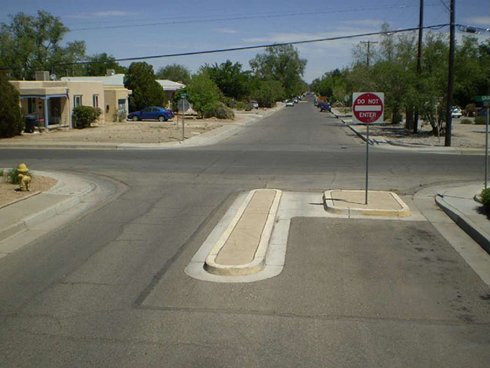
Figure 3.23.3. Half Closure Blocking Exit from Side Street
(Source: James R. Barrera)
| Appropriate Application – Half Closure | |
| Type of Street | Appropriate for a subdivision or local street; half closure placed on a collector street diminishes the ability of the street to serve its collector function Appropriate for use at a local road intersection with a collector or arterial street because those roadways should be better able to accommodate the diverted traffic (see Figure 3.23.4) Can be appropriate in both an urban and suburban setting |
| Intersection or Roadway Segment | Applicable only at an intersection; a motorist encountering a half closure placed midblock could bypass the measure in the wrong direction instead of turning around and backtracking |
| Roadway Cross-Section | Appropriate only for a two-way street Typically found only on a roadway with an urban cross-section (i.e., curb and gutter) Can be applied both with and without a bicycle facility Can be applied on a roadway with on-street parking |
| Speed Limit | As long as there is adequate advance warning, the appropriate speed limit is not constrained; South Carolina uses a 30 mph maximum; the Pennsylvania maximum is 25 mph |
| Vehicle Traffic Volume | Can be appropriate if the traffic volume is relatively low; Pennsylvania uses a maximum of 3,500 daily vehicles |
| Emergency Route | Not appropriate along a primary emergency vehicle route or street that provides access to a hospital or emergency medical services |
| Transit Route | Typically not appropriate along a bus transit route (unless for a oneway leg) |
| Access Route | Not appropriate along a primary access route to a commercial or industrial site |
| Grade | Can be installed on a crest vertical curve only if there is adequate stopping sight distance or if appropriate warning signs are provided Maximum grade should comply with local standards and criteria; Delaware uses a maximum grade of 6 percent |

Figure 3.23.4. Half Closure Blocking Entry to Side Street with Bicycle Cut-Through
(Source: Jeff Gulden)
| Effects and Issues – Half Closure | |
| Vehicle Speed | Narrows pavement width through closure island in the open direction; traffic speeds likely to decrease slightly |
| Vehicle Volume | All traffic in one direction prevented from using the street and diverted to parallel streets; volume reduction in the range of 40-60 percent is typical (see Figure 3.23.5) |
| Pedestrian Safety and Mobility | Pedestrian safety presumably improves with both reduction in vehicle volume and reduction in roadway crossing distance; pedestrian access through half closure can be accommodated by providing a gap in feature with curb ramps Refer to Module 6 for additional discussion |
| Bicyclist Safety and Mobility | Bicyclist safety presumably improves with reduction in vehicle volume Refer to Module 6 for additional discussion |
| Motorist Safety and Mobility | Cause some motorists to shift to different and less direct travel path Potential issue with opportunity for motorist to not adhere to one-way restriction:
Violations more likely to occur during periods with low traffic volume |
| Emergency Vehicle Safety and Mobility | Emergency response vehicles can maneuver around a half closure when responding to an emergency Refer to Module 5 for additional discussion |
| Large Vehicle Safety and Mobility | A half closure restricts large vehicles from travelling one way or the other along a section of a street; access may be reduced Refer to Module 5 for additional discussion |
| Accessibility of Adjacent Property | Reduces overall street connectivity and causes the need for more circuitous routing to and from a property; accessibility of adjacent property is adversely affected Can require removal of some on-street parking, reducing accessibility of adjacent property |
| Environment | Can be used as landscaping opportunity |
| Design Issues | Potential drainage issues if gutter is blocked |

Figure 3.23.5. Half Closure Allowing Exit from Side Street
(Source: James R. Barrera)
A half closure should provide a full lane width in the open direction and sufficient curb radii at the entrance intersection to permit the design vehicle to make a turn at the treated intersection without encroaching onto a curb or island.
The most common application of a half closure blocks entry to the side street from the main street and permits side street traffic to enter the main street. It is called an exit-only closure. For an exit-only half closure, movement prohibition and DO NOT ENTER signs are required to advise approaching traffic of the closure. One-Way signs should be used to advise traffic on the main street that a turn into the closed street is not permitted. An example is shown in Figure 3.23.6.
An entrance-only half closure is less common because it can trap side street traffic attempting to access the main street. The closure requires a motorist to use a different set of roadways than the closed section. The potential safety problem is that a motorist, after approaching within eyesight of the main street, may be tempted to use the short wrong-way section adjacent to the half closure. For an entrance-only half closure, appropriate cul-de-sac signage should be provided.
The main street and side street sides of the half closure island should have a vertical curb to discourage an unauthorized motorist from trying to traverse it.
A half closure island may have an opening roughly four feet wide on the curb side of the street to allow drainage flow and to permit bicyclists, but not motorists, to pass through the barrier in the closed direction. The four foot width is sufficient if bordered by rolled curbs. If the bicyclist cutout is bordered on both sides by vertical curbs, the channel width should be at least five feet. Signage that denotes the permissible use of the cutout by bicyclists s hould be provided.
There are no pavement markings specific to this measure. A sample design detail is presented in Figure 3.23.7.
Figure 3.23.6. Example Signage for a Half Closure Blocking Entry to a Side Street
(Source: James R. Barrera)
. There is a One Way sign labeled on the island. The curve near the lane is labeled R=3' (typ.). A set of ramps and cut is indicated where the crosswalk would cross over the median. A bike lane between the median and the left curb is labeled. The original curbline is indicated.")
Figure 3.23.7. Sample Design for Half Closure
(Source: Delaware Department of Transportation)
Median barrier and forced turn island are two variations of physical turn restrictions at an intersection that can be used to eliminate specific traffic flows (in particular, cut-through traffic) from entering or exiting a side street.
A median barrier is a raised island placed through an intersection, along the centerline of a roadway (often the higher-order roadway), preventing a motorist from traveling straight through the intersection on the side street (see Figure 3.24.1). A median barrier can be designed to allow turns to and from the main street, while preventing through traffic from the side street from crossing the main roadway.
A forced turn island is a raised island that blocks certain movements on approaches to an intersection (see Figure 3.24.2). It can force a motorist to turn right from the side street (by blocking left-turn and through movements).
A forced turn island is a raised traffic island, typically triangular in shape, placed at the mouth of an intersection. It channels traffic to the right and blocks left and through movements. It can constrain traffic entering the intersection on the approach leg with the island, exiting the intersection on the approach leg, or both. Its turning traffic restrictions are similar to those of a median barrier.
Depending on its design, a median barrier can also reduce vehicle speed on the main street through lane narrowing (it then, in traffic calming terms, is also a median island). These physical restrictions are more effective than those that rely solely on signage and markings. They also do not require enforcement.
A single median barrier or single forced turn island may simply shift traffic (and its associated problems and issues) onto other local streets. In order to prevent a traffic shift from one local street to another, a series of median barriers or comprehensive set of forced turn islands can be installed at all minor street intersections along a section of the major street.
[A median barrier is also called a median diverter, intersection barrier, intersection diverter and island diverter]
[A forced turn island is also called a channelization island, pork chop, and right-turn island.]
[Other physical measures used to restrict intersection movement include star diverters and truncated diagonal diverters.]
[Median barrier versus median island – purpose of median barrier is to prevent certain turn movements and reduce traffic volume; purpose of median island is to narrow travel lanes and reduce vehicle speed]

Figure 3.24.1. Median Barrier Schematic
(Source: Delaware Department of Transportation)

Figure 3.24.2. Forced Turn Island Schematic
(Source: Delaware Department of Transportation)
| Appropriate Application – Median Barrier and Forced Turn Island | |
| Type of Street | [Median Barrier] Appropriate for installation on an arterial or collector street to prevent turns into or out of a minor collector, local, or subdivision street [Forced Turn Island] Can be appropriate on any type of street Can be appropriate in both an urban and suburban setting |
| Intersection or Roadway Segment | Applicable only at an intersection |
| Roadway Cross-Section | Can be used on both a one-way and two-way street Typically found only on a roadway with an urban cross-section (i.e., curb and gutter) but it is not necessary Can be applied both with and without a bicycle facility (see Figures 3.24.3 and 3.24.4) Can be applied on a roadway with on-street parking |
| Speed Limit | Maximum speed limit on side street is typically 25 mph |
| Vehicle Traffic Volume | No maximum volume for side street blocked by median barrier or configured with forced-turn island |
| Emergency Route | Not appropriate if primary emergency vehicle route is blocked or side street provides access to a hospital or emergency medical services |
| Transit Route | Not appropriate if bus transit route is blocked unless route can be altered |
| Access Route | Not appropriate if primary access route to a commercial or industrial site is blocked |
| Grade | Can be installed on a crest vertical curve only if there is adequate stopping sight distance or if appropriate warning signs are provided Maximum grade should comply with local standards and criteria |

Figure 3.24.3. Median Barrier with Bicycle Boulevard Cut-Through
(Source: Eugene Jud, Jud Consultants)

Figure 3.24.4. Narrow Median Barrier with Cut-Throughs
(Source: James R. Barrera)
| Effects and Issues – Median Barrier and Forced Turn Island | |
|---|---|
| Vehicle Speed | Not expected to reduce vehicle speed on local street approach to intersection; could reduce speed on major street leg of intersection [provide link to 3.18 Median Island] |
| Vehicle Volume | Can reduce traffic volume on local street approach to intersection; left-turning and straight-through traffic from local street is redirected to either (1) turn right onto the major street or (2) follow another local street that can enable a left turn or to cross to the other side of the major street Because of potential for significant impact on traffic patterns, can be controversial |
| Pedestrian Safety and Mobility | Pedestrian safety on local street presumably improves with reduction in vehicle volume for some pedestrian-vehicle conflict areas; a corner extension could shorten the street crossing distance and further improve pedestrian safety If sufficient in width to offer a pedestrian refuge area, pedestrian safety and mobility can be improved (see Figure 3.24.5) Pedestrian access can be accommodated by providing gap in feature with curb ramps Refer to Module 6 for additional discussion |
| Bicyclist Safety and Mobility | Bicyclist safety on local street presumably improves with reduction in vehicle volume Bicyclist access can be accommodated by providing a gap in the feature; opening can be level with or ramped to the pavement; appropriate bicycle-specific signing and striping can be installed to direct bicycle flow Refer to Module 6 for additional discussion |
| Motorist Safety and Mobility | Can improve motorist safety at the intersection by removing some conflicting traffic movements |
| Emergency Vehicle Safety and Mobility | Restricts emergency vehicles from passing straight through or turning left from the minor street and from turning left into the minor street; emergency access and response time is affected Refer to Module 5 for additional discussion |
| Large Vehicle Safety and Mobility | Restricts large vehicles from passing straight through or turning left from the minor street and from turning left into the minor street Does not limit mobility for a right-turning transit vehicle Refer to Module 5 for additional discussion |
| Accessibility of Adjacent Property | Blockage of vehicular traffic through intersection affects both through traffic and local traffic attempting to access the local street system and its adjacent properties; reduces overall street connectivity and requires more circuitous routing May require removal of on-street parking along the major street legs of intersection May block some turns into major street driveways that are close to the intersection, thereby reducing property accessibility |
| Environment | Can be used to visually enhance the street with landscaping, provided visibility of pedestrian in crossing is not compromised |

Figure 3.24.5. Median Barrier with Pedestrian Refuge and Bicycle Cut-Through
(Source: Steven Vance)
The design of a median barrier or forced turn island should consider the right turn curb radii needed for a design vehicle unless the median is traversable.
A median barrier should have openings of sufficient width for bicyclists and pedestrians to pass through the median (on a marked crosswalk) but not so wide to enable a motor vehicle to make a prohibited turn movement. A common width used for median barrier openings is eight feet.
If the forced turn island has sufficient width, it can be designed to provide pedestrian refuge for crossing the affected intersection approach leg.
If a median barrier has sufficient width, it can be landscaped for aesthetic reasons and to reinforce the perception that the barrier is not to be traversed, if sufficient width is available. If it is necessary to provide access through the median barrier for an emergency vehicle, a clear width of at least 10 feet should be left free of landscaping and the barrier opening should be clearly signed that it is for emergency vehicles only. A vertical deflection could be added to further discourage non-emergency vehicle usage, but the introduction of jarring of emergency vehicles could hinder emergency access.
The median barrier should extend a sufficient distance (15 to 25 feet is typical) beyond the intersection to discourage a main street motorist from attempting to drive to the left of the median in order complete a left turn to the side street.
Figures 3.24.6 and 3.24.7 illustrate a combination of forced turn islands and a truncated median barrier that block through traffic movements on the side streets, but allow all other through and turning movements at the intersection.
A typical design for a median barrier is presented in Figure 3.24.8. A typical design for a forced turn island is presented in Figure 3.24.9.

Figure 3.24.6. Forced Turn Island Blocking Side Street Through Movements and Allowing All Turns
(Source: Rick Perez)

Figure 3.24.7. Forced Turn Island Blocking Side Street Through Movements and Allowing All Turns – Aerial
(Source: Google Earth)
\". The right oval has a sign labeled \"R4-7\" on its right end and the right end has a line pointing to it with the text \"R=3' (typ.)\". The curve of sidewalk on the bottom left quadrant has a sign on it labeled \"R7-4\". The bottom right quadrant has a label pointing to the length of the median barrier on the right and has the text \"15'-25' (typ.)\". The bottom of the diagram contains the text \"Note: 1. All signing and striping shall conform to the latest edition of the DE MUTCD.\"")
Figure 3.24.8. Sample Design for Median Barrier
(Source: Delaware Department of Transportation)
\". In the bottom right quadrant there is a label pointing to the narrow right turn crosswalk with the text \"Width varies with inner curb radius and angle of turn.\" A label points to a solid line running across the right turn lane with the text \"Stop bar set back from crosswalk 4'\". The curve of sidewalk on the bottom right quadrant has a sign on it labeled \"R3-5R\". The bottom of the diagram contains the text \"Note: 1. All signing and striping shall conform to the latest edition of the DE MUTCD.\" On the right side of the bottom of the diagram there is a rectangle containing a double curved arrow pointing to the left and right which is branched off of a single line. It is labeled with the text \"*Optional Movement Lane Control Sign (R4-6LR)\".")
Figure 3.24.9. Sample Design for Forced Turn Island
(Source: Delaware Department of Transportation)

