U.S. Department of Transportation
Federal Highway Administration
1200 New Jersey Avenue, SE
Washington, DC 20590
202-366-4000
| < Previous | Table of Content | Next > |
Section 1429 of the FAST Act requires the Secretary of Transportation to study ID methods that transportation agencies can use to collect data about their roadside highway safety hardware. Transportation agencies can use these ID methods to evaluate the in-service performance of the roadside safety hardware and improve the data collected about the hardware. Section 1429 states the following:
SEC. 1429. IDENTIFICATION OF ROADSIDE HIGHWAY SAFETY HARDWARE DEVICES.
(a) STUDY.–The Secretary shall conduct a study on methods for identifying roadside highway safety hardware devices to improve the data collected on the devices, as necessary for in-service evaluation of the devices.
(b) CONTENTS.–In conducting the study under subsection (a), the Secretary shall evaluate identification methods based on the ability of the method–
(1) to convey information on the devices, including manufacturing date, factory of origin, product brand, and model;
(2) to withstand roadside conditions; and
(3) to connect to State and regional inventories of similar devices.
(c) IDENTIFICATION METHODS.–The identification methods to be studied under this section include stamped serial numbers, radio-frequency identification, and such other methods as the Secretary determines appropriate.
(d) REPORT TO CONGRESS.–Not later than January 1, 2018, the Secretary shall submit to Congress a report on the results of the study under subsection (a).
This study is designed to satisfy the Section 1429 requirement. The study included a literature review, a review of the practices of transportation agencies and other industries, and input from an expert panel. The roadside safety hardware expert panel included manufacturers, installers, researchers from across the United States, and staff members from three State departments of transportation. The practitioners considered parameters that agencies could use to effectively select ID methods and improve their capability to implement ISPE or asset management programs.
This first chapter gives a brief background of roadside safety hardware, potential opportunities arising from identifying and documenting this hardware, and gaps in current methods of identifying and documenting information about roadside safety hardware.
Roadside safety hardware is part of the highway infrastructure that functions to reduce crash severity. Roadway departures accounted for over half of the 35,092 traffic fatalities in the United States in 2015.(3) Roadside design provides for a clear, recoverable area where feasible, and where roadsides cannot be designed free of fixed objects, crashworthy roadside safety hardware is used to reduce risk. Despite improved design and crash testing of hardware, approximately 3 percent of U.S. traffic fatalities occur in vehicles where the most harmful event involved the hardware itself.*
The AASHTO Roadside Design Guide provides information on designing roadways to reduce crash risk and severity. Roadside barriers are designed to contain and redirect vehicles. Barriers are installed only in locations where there is potential for greater harm, such as crossing into oncoming traffic, rolling over on a steep slope, or hitting trees. When roadside assets are necessary, such as signs and luminaires, supports have safety design features to break away in a crash so that they pose minimal risk to motorists.
Before discussing and evaluating ID methods, it is important to understand the different types of roadside safety hardware and their functions. This section defines the following common hardware and gives some examples:
The AASHTO Roadside Design Guide defines a barrier as:
A device which provides a physical limitation through which a vehicle would not normally pass. It is intended to contain or redirect an errant vehicle.(1)
The term barrier in this report includes:
Figure 1 shows an example of longitudinal barrier.
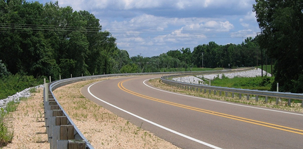
Figure 1. Photo. Example of longitudinal barrier.
The AASHTO Roadside Design Guide defines a terminal as:
…a crashworthy anchorage, a device used to anchor a flexible or semi-rigid barrier to the ground. Being crashworthy, terminals are normally used at the end of a barrier that is located within the clear zone or that is likely to be impacted by errant vehicles.(1)
Figure 2 shows an example of a barrier terminal.
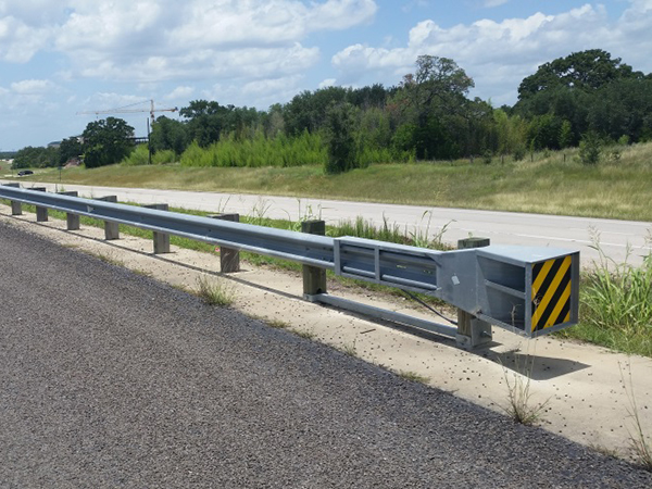
Figure 2. Photo. Example of a barrier terminal.
The AASHTO Roadside Design Guide defines crash cushions, also known as impact attenuators, as:
…typically attached to or placed in front of concrete barriers (median barriers, roadside barriers, or bridge railings) or other rigid fixed objects, such as bridge piers, to prevent an errant vehicle from impacting fixed objects by gradually decelerating the vehicle to a safe stop or by redirecting the vehicle away from the obstacle.(1)
Figure 3 shows an example of a crash cushion.
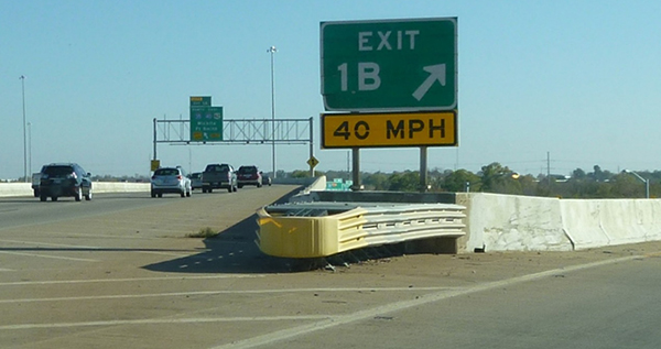
Figure 3. Photo. Example of a crash cushion.
The AASHTO Roadside Design Guide defines the term breakaway as:
A design feature which allows a device such as a sign, luminaire, or traffic signal support to yield or separate upon impact. The release mechanism may be a slip plane, plastic hinges, fracture elements, or a combination of these.(1)
Breakaway hardware for this report includes supports for signs, luminaires, and traffic signals. Figure 4 shows an example of breakaway hardware, specifically a sign support.
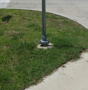
Figure 4. Photo. Example of breakaway hardware.
Crash testing of safety hardware is a vital first step in understanding how hardware will perform. However, crash testing is performed under ideal conditions, which are not always representative of every real-world condition across the entire roadway network. And while crash-testing parameters are set to test the limits of performance of hardware, some crashes may occur at higher speeds, different angles, or different vehicle parameters than the crash tests. The ISPE, continuous monitoring, and asset management allow agencies to gather more data about how safety hardware performs in practice.
The AASHTO Roadside Design Guide states:
…in-service evaluation is a very important step when assessing the impact performance of a new or extensively modified safety feature [or hardware]. The purpose of in-service evaluation is to determine and document the manner in which the safety feature [or hardware] performs within a broad range of collisions and real-world conditions, such as environmental, operational, and maintenance situations for typical site and traffic conditions.
The Roadside Design Guide lists the following factors that can cause differences between field performance and crash test results:
The ISPEs allow transportation agencies to identify overall performance, potential weaknesses, and design problems of roadside safety hardware. The FHWA and AASHTO encourage agencies to evaluate in-service hardware and continuously monitor it to assess its field performance. However, agencies themselves determine how they monitor and assess in-field performance.
ISPEs may include the following elements:
Even after the hardware has undergone a successful ISPE, the AASHTO Manual for Assessing Safety Hardware strongly recommends continuous monitoring. Continuous monitoring requires examining highway and traffic data, maintenance records, roadside feature inventory data, crash data, and other components for periodic analysis.(4)
Existing asset management practices used by transportation agencies may be an efficient means of accomplishing ISPE. Section 101(a)(2) of Title 23 of the United States Code defines asset management as:
…a strategic and systematic process of operating, maintaining, and improving physical assets, with a focus on both engineering and economic analysis based upon quality information, to identify a structured sequence of maintenance, preservation, repair, rehabilitation, and replacement actions that will achieve and sustain a desired state of good repair over the lifecycle of the assets at minimum practicable cost.(2)
The objective of asset management is to make decisions based on quality information and focused on engineering and business practices for resource allocation and utilization.(5)
Current requirements in asset management are for transportation agencies to develop asset management plans for pavement and bridges. However, expanding asset management to safety assets is an opportunity to obtain quality data for analysis in an ISPE program.
Quality data are key components of asset management and analyses such as ISPEs. The industry generally divides data collection techniques for asset management into three categories:
Currently, these are the state-of-the-practice techniques for collecting information about roadway assets, including roadside safety hardware.
Manual Collection
Manual collection may use handheld computers, global positioning system (GPS) units, or pen-and-paper records. Data collectors may stop at a particular location and survey the condition and location of each asset, or they may conduct a driving survey.(6) The means of recording data may depend on the level of detail desired by the agency.
Automated Collection
Automated collection involves a vehicle equipped with technologies to identify and document transportation assets. The vehicle may be equipped with video cameras, a GPS unit, laser imaging detection and ranging (LIDaR), and computer hardware to capture, store, and process collected data.(6)
Remote Collection
Remote collection uses photo logs, video logs, and satellite images. With remote collection, the images are used in conjunction with ground information to describe the location, condition, attributes, and characteristics of the roadway asset.(6) The quality of the remote data collection may be dependent on existing records about the asset.
Identifying and documenting safety hardware can facilitate ISPE. As discussed previously, there are various methods to collect this information, including using barcodes, RFID, and serial numbers. For true facilitation of ISPE, transportation agencies must evaluate suitable ID methods that provide:
This report provides information on determining how the three ID methods (barcodes, RFID, and serial numbers) might improve a transportation agency's capability to identify and document safety hardware.
Traditional asset management practices typically look at the transportation system as a whole–tracking system conditions, needs, and performance; developing costs for maintaining and preserving existing assets; and determining when to undertake an action on an asset.(5) For safety hardware, an asset management system needs to be able to provide specific, unique information about the hardware. This information could describe the hardware (as a system), installed components, the manufacturer, the installer, or the location.
This information can be analyzed over time by many characteristics and can help transportation agencies develop performance profiles, which aid in decision making. The additional cost of these capabilities and the complexity of the databases and analysis procedures needed to use them must be considered as well. Methods need to match the capabilities and available funds of the agencies that would potentially use them.
Another consideration is the capability to follow roadside safety hardware and components from their origination at a manufacturer's factory to their final disposition in a crash, system upgrade, or other reason for replacement. The concept and value of event-based tracking were heavily considered during this study, including the following:
Another aspect considered in the evaluation of ID methods is the ability of an ID method to support robust data sets for use with ISPE and asset management analysis. Robust data may allow researchers to analyze safety hardware to determine which performs better under different roadside and crash conditions. The data could also speed up the ISPE process and provide more accurate data about installation and maintenance of safety hardware.
With the many cloud-based connectivity options available, the ability of an ID method to provide near-real-time safety hardware information is another important consideration in the evaluation. Having information that can be accessed remotely and updated actively reduces labor, provides better quality information to associate with crash data, and may result in more timely analysis.
Gaps in the current processes used by transportation agencies to identify and document roadside safety hardware include the following:
This report addresses these gaps by investigating ID methods with the potential to improve data collection and storage necessary for ISPE.
This report summarizes findings in the following chapters:
* Based on data from the National Highway Traffic Safety Administration's Fatality Analysis Reporting System (FARS) database. Roadside safety hardware includes all longitudinal barriers, barrier terminals, crash cushions, and traffic sign supports.
| < Previous | Table of Content | Next > |

